Table of Contents:
Introduction: simple pulse oximeter
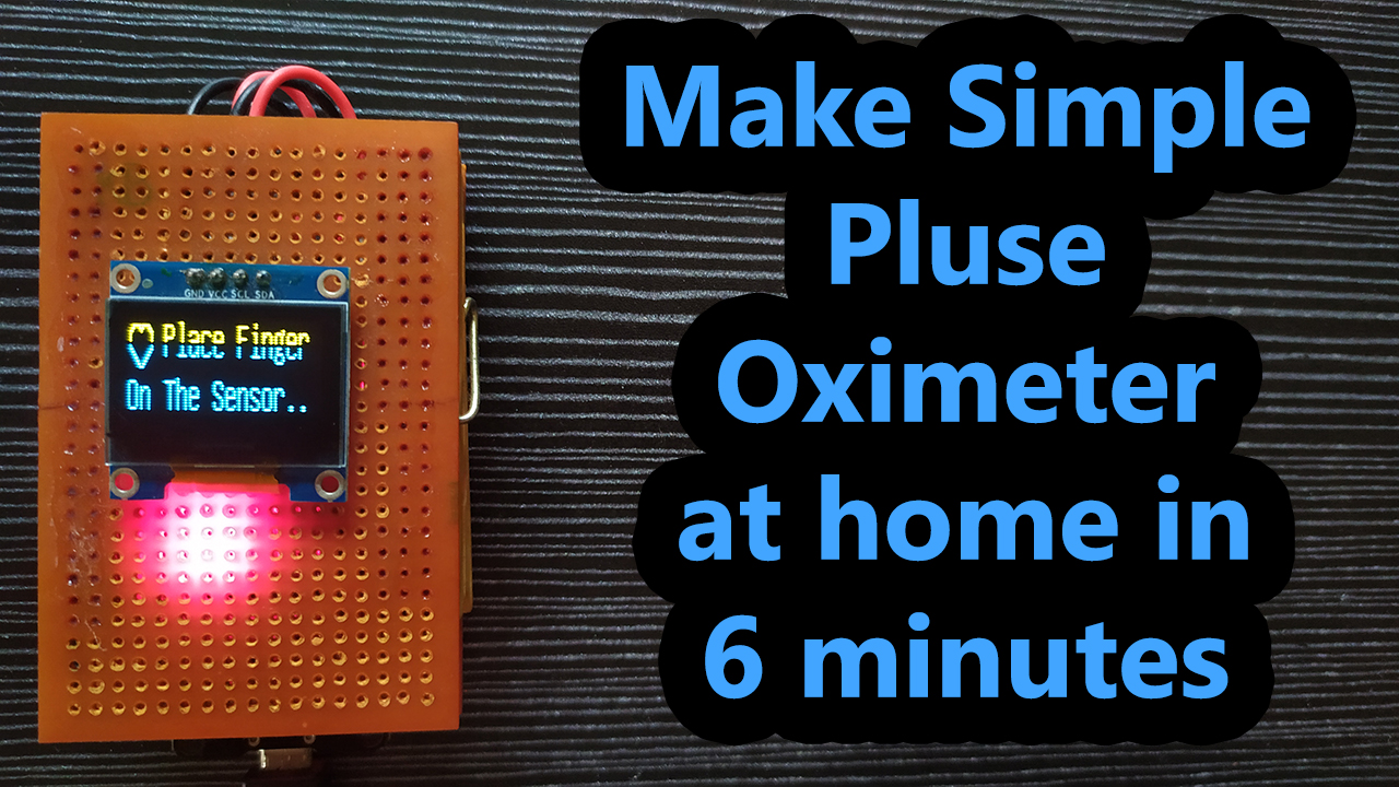
In this video, I’m gonna show you how to make a simple pulse oximeter at home by doing it yourself.
This device will read SpO2 and Heart data from the MAX30100 sensor and display it on the OLED Display.
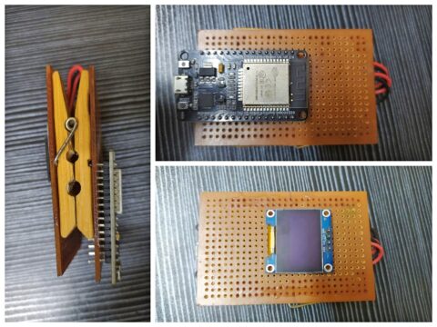
I’m gonna use a conventional pulse oximeter-like device for this project, which I made in one of my previous videos.
but don’t worry I will explain to you how to make this with just 2 cloth hanging clips and superglue, which are always available at home.
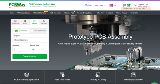
Let’s take a moment and thank PCBWay.com, The sponsor of the video.
PCBWay.com is an Online PCB manufacturing Enterprise, which produces the best in quality PCBs for just 5 dollars.
PCBWay.com offers all services you need to make Hardware for your IoT or Embedded Devices.
If you have a similar requirement, do check out their website for more details using this link.
So, without wasting further time, Let’s see how to build this simple pulse oximeter.
Video Tutorial: Simple Pulse Oximeter.
This tutorial is also available in video format, you can watch the below videos or continue reading this article.
Required Components: Simple Pulse Oximeter
1. ESP32 Module (Buy from Amazon)
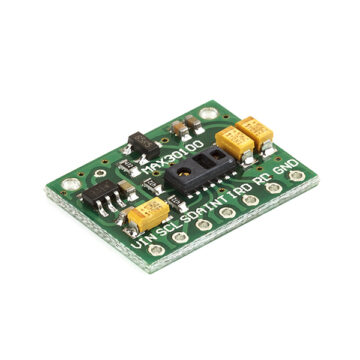
2. MAX30100 pulse oximeter sensor (Buy from Amazon)
3. 4.7k ohm resistors (Buy from Amazon)
4. OLED Display (Buy from Amazon)
5.Vero Boards (Buy from Amazon)
6. Connecting wires. (Buy from Amazon)
7. Soldering Kit (Buy from Amazon)
8. Cloth Hanging Clips (Buy from Amazon)
Overview: Pulse Oximeter and Heart-Rate Sensor (MAX30100)
Sensor Description:
The MAX30100 is complete pulse oximetry and heart-rate sensor system solution designed for the demanding requirements of wearable devices. The MAX30100 pro-vides very small total solution size without sacrificing optical or electrical performance. Minimal external hardware components are needed for integration into a wearable device. The MAX30100 is fully configurable through software registers, and the digital output data is stored in a 16-deep FIFO within the device. The FIFO allows the MAX30100 to be connected to a microcontroller or microprocessor on a shared bus, where the data is not being read continuously from the device’s registers.
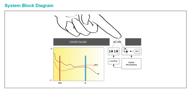
SpO2 Subsystem
The SpO2 subsystem in the MAX30100 is composed of ambient light cancellation (ALC), 16-bit sigma-delta ADC, and a proprietary discrete-time filter. The SpO2 ADC is a continuous-time oversampling sigma-delta converter with up to 16-bit resolution. The ADC output data rate can be programmed from 50Hz to 1kHz. The MAX30100 includes a proprietary discrete-time filter to reject 50Hz/60Hz interference and low-frequency residual ambient noise
Temperature Sensor
The MAX30100 has an on-chip temperature sensor for (optionally) calibrating the temperature dependence of the SpO2 subsystem. The SpO2 algorithm is relatively insensitive to the wavelength of the IR LED, but the red LED’s wavelength is critical to correct interpretation of the data. The temperature sensor data can be used to compensate for the SpO2 error with ambient temperature changes.
LED Driver
The MAX30100 integrates red and IR LED drivers to drive LED pulses for SpO2 and HR measurements. The LED current can be programmed from 0mA to 50mA (typical only) with proper supply voltage. The LED pulse width can be programmed from 200μs to 1.6ms to optimize measurement accuracy and power consumption based on use cases
Benefits and Features
●Complete Pulse Oximeter and Heart-Rate Sensor Solution Simplifies Design
• Integrated LEDs, Photo Sensor, and High-Performance Analog Front -End
• Tiny 5.6mm x 2.8mm x 1.2mm 14-Pin Optically Enhanced System-in-Package
●Ultra-Low-Power Operation Increases Battery Life for Wearable Devices
• Programmable Sample Rate and LED Current for Power Savings
• Ultra-Low Shutdown Current (0.7μA, typ)
●Advanced Functionality Improves Measurement Performance
• High SNR Provides Robust Motion Artifact Resilience
• Integrated Ambient Light Cancellation
• High Sample Rate Capability• Fast Data Output Capability
Applications
●Wearable Devices
●Fitness Assistant Devices
●Medical Monitoring Devices
Circuit Diagram: DIY Intelligent Pulse Oximeter
Here Is the circuit diagram to interface Max30100 and OLED display with ESP32, Since we are using the I2C protocol, both modules can be interfaced with ESP32 with the same Pins. if you want to know, why do we need to solder external pull-up resistors? follow this tutorial.
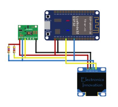
After Connections, the circuit should be something like this. Don’t worry, I have guided you step by step to make this arrangement in the video tutorial you can refer to the video tutorial for more info.
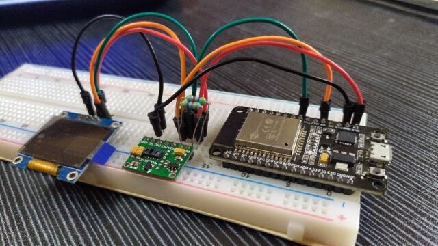
If you are not interested to make this kind of arrangement, you can still use the breadboard to connect the device as shown here.
Programming part:
Here is the code to read data from the Max30100 sensor and Display it on the OLED Display.
Before you upload the code to ESP32, Make sure you have downloaded all the required libraries.
These two libraries are not available on the Arduino Libraries Manager.
You have to download from the git hub and then Install using add zip library feature on the Arduino IDE.
Library download links:
Source Code:
#include "MAX30100_PulseOximeter.h"
#include <U8g2lib.h>
#include <Wire.h>

#define REPORTING_PERIOD_MS     500
U8G2_SSD1306_128X32_UNIVISION_F_HW_I2C u8g2(U8G2_R0);

PulseOximeter pox;

const int numReadings=15;
float filterweight=0.5;
uint32_t tsLastReport = 0;
uint32_t last_beat=0;
int readIndex=0;
int average_beat=0;
int average_SpO2=0;
bool calculation_complete=false;
bool calculating=false;
bool initialized=false;
byte beat=0;

// Callback (registered below) fired when a pulse is detected
void onBeatDetected()
{
  show_beat();
  last_beat=millis();
}

void show_beat()
{
  u8g2.setFont(u8g2_font_cursor_tf);
  u8g2.setCursor(8,10);
  if (beat==0) {
    u8g2.print("_");
    beat=1;
  }
  else
  {
    u8g2.print("^");
    beat=0;
  }
  u8g2.sendBuffer();
}

void initial_display()
{
  if (not initialized)
  {
    u8g2.clearBuffer();
    show_beat();
    u8g2.setCursor(24,12);
    u8g2.setFont(u8g2_font_unifont_t_bengali);
    u8g2.print("Place Finger");
    u8g2.setCursor(0,30);
    u8g2.print("On The Sensor..");
    u8g2.sendBuffer();
    initialized=true;
  }
}

void display_calculating(int j)
{
  if (not calculating) {
    u8g2.clearBuffer();
    calculating=true;
    initialized=false;
  }
  show_beat();
  u8g2.setCursor(24,12);
  u8g2.setFont(u8g2_font_unifont_t_bengali);
  u8g2.print("Measuring....");
  u8g2.setCursor(0,30);
  for (int i=0;i<=j;i++) {
    u8g2.print(".");
  }
  u8g2.sendBuffer();
}
void display_values()
{
  u8g2.clearBuffer();
  u8g2.setFont(u8g2_font_unifont_t_bengali);

  u8g2.setCursor(65,12);
  u8g2.print(average_beat);
  u8g2.print(" Bpm");
  u8g2.setCursor(0,30);
  u8g2.print("SpO2 ");
  u8g2.setCursor(65,30);
  u8g2.print(average_SpO2);
  u8g2.print(" %");
  u8g2.sendBuffer();
}

void calculate_average(int beat, int SpO2)
{
  if (readIndex==numReadings) {
    calculation_complete=true;
    calculating=false;
    initialized=false;
    readIndex=0;
    display_values();
  }

  if (not calculation_complete and beat>30 and beat<220 and SpO2>50) {
    average_beat = filterweight * (beat) + (1 - filterweight ) * average_beat;
    average_SpO2 = filterweight * (SpO2) + (1 - filterweight ) * average_SpO2;
    readIndex++;
    display_calculating(readIndex);
  }
}

void setup()
{
    Serial.begin(115200);
    Wire.begin(4,5);
    u8g2.begin();
    pox.begin();
    pox.setOnBeatDetectedCallback(onBeatDetected);
    initial_display();
}

void loop()
{
    // Make sure to call update as fast as possible
    pox.update();
    if ((millis() - tsLastReport > REPORTING_PERIOD_MS) and (not calculation_complete)) {
        calculate_average(pox.getHeartRate(),pox.getSpO2());
        tsLastReport = millis();
    }
    if ((millis()-last_beat>5000)) {
      calculation_complete=false;
      average_beat=0;
      average_SpO2=0;
      initial_display();
    }
}
Uploading Code:
Connect the ESP32 with the laptop and Select the Board type ESP32 Dev Module and Right port from the tools menu.

After that Click on Uploading Button.
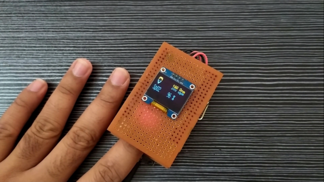
After Successful Uploading You can see the Program in action.
Just Plugin this Module onto the finger and Measure the SpO2 and Heart Rate of your body seamlessly.
sir can you make gerber file for this project i need that
PLEASE check your circuit diagram and actual connection ,huge difference in both ,in circuit you connect to vcc and in actual you connect to rd …wOWWWW ,in that we lostt the path thnk you for your support ..
finally we end up with anew problem ,,,thnk you