Table of Contents:
Introduction:
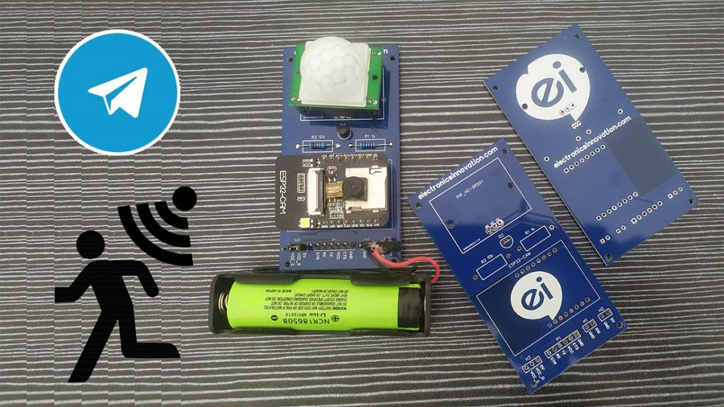
In this video, we are going to see how to make “Motion triggered Telegram Alert device with help of ESP32 camera & PIR Motion sensor”.
This device will capture an image and send it to the Telegram whenever the motion detected.
PCBway:
The PCBs I’m gonna use in this video are ordered from PCBway.com, PCBWAY is one of the best PCB manufacturers in the current industry.
PCBway is offering services like PCB prototype, SMD Stencil, PCB assembly, Flexible PCBs & Advanced PCBs.
At PCBway.com we can get 10 pieces of 2 layered PCBs at just $5 with 24 hours build time.
The Best part of PCBway is the Instant quote feature, just enter the PCB size, choose the quantity, layers, and thickness. That’s it, we will get the instant quote. place an order by clicking on saving to cart.

Video Tutorial: Motion Triggered Telegram Alert
This tutorial is also available in video format, you can watch the below videos or continue reading this article.
Required components:
- ESP32 Camera (Buy Online)
- FTDI Programmer Module (Buy Online)
- PIR Motion Sensor (Buy Online)
- NPN Transistor (Buy Online)
- 1k and 10k Resistors (Buy Online)
Introduction to ESP32-Cam:
The ESP32-Cam is a very small camera module with the ESP32-S chip that costs less than $10. Besides the OV2640 camera and several GPIOs to connect peripherals, it also features a microSD card slot that can be useful to store images taken with the camera or to store files to serve to clients.

ESP32-Cam Components/parts:

The ESP32-Cam doesn’t have any onboard USB connector like NodeMCU-ESP8266 comes with an onboard micro-USB connector, so you need an FTDI programmer to upload code through the U0R and U0T pins (serial pins).

Feature of ESP32 Camera:
Here is a list with the ESP32-Cam features:
- The smallest 802.11b/g/n Wi-Fi BT SoC module
- Low power 32-bit CPU, can also serve the application processor
- Up to 160MHz clock speed, summary computing power up to 600 DMIPS
- Built-in 520 KB SRAM, external 4MPSRAM
- Supports UART/SPI/I2C/PWM/ADC/DAC
- Support OV2640 and OV7670 cameras, built-in flash lamp
- Supports image WiFI upload
- Support TF card
- Supports multiple sleep modes
- Embedded Lwip and FreeRTOS
- Supports STA/AP/STA+AP operation mode
- Support Smart Config/AirKiss technology
- Support for serial port local and remote firmware upgrades (FOTA)
ESP32-Cam Pinout(AI-Thinker module):

There are three GND pins and two pins for power: either 3.3V or 5V.
GPIO 1 and GPIO 3 are the serial pins. You need these pins to upload code to your board. Additionally, GPIO 0 also plays an important role, since it determines whether the ESP32 is in flashing mode or not. When GPIO 0 is connected to GND, the ESP32 is in flashing mode.
Circuit Diagram:
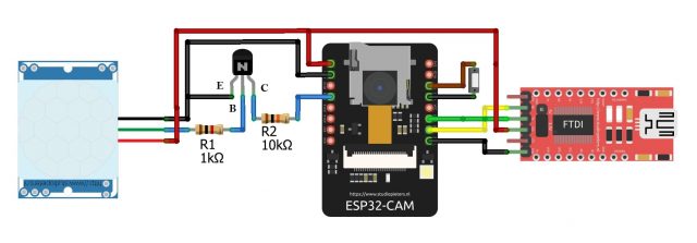
Here is the circuit for Motion Triggered Telegram Alert Device with ESP32 Camera, The intermediate trigger circuit between Motion sensor and ESP32 will generate an interrupt to wakeup the ESP32-Cam Module when the motion is detected by PIR Motion Sensor. since ESP32-Cam doesn’t have any onboard USB connector as NodeMCU-ESP8266 comes with an onboard micro-USB connector, we will use this FTDI programmer to upload code through the U0R and U0T pins (serial pins). GPIO0 (IO0) needs to be connected to GND, to put ESP32-Cam in the flash mode so that we can upload code.
Schematic Diagram:
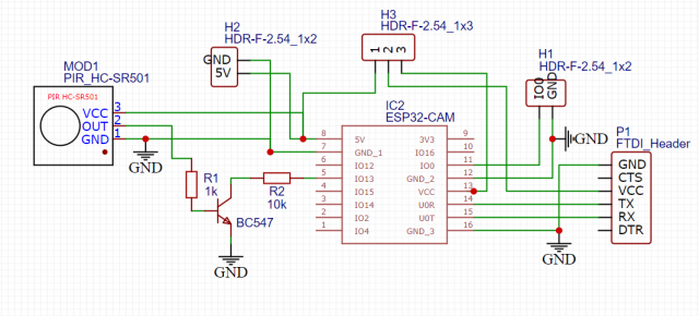
I have implemented the schematic diagram of the same circuit on EasyEDA.com.
MOD1 is the PIR Motion sensor, Intermediate Trigger circuit, ESP32 – Cam, P1 Header to interface with FTDI Module, H1 header to short IO0 and GND pins. H3 header will help us in selection 3.3v or 5v from FTDI, H2 Header is used to supply the input power either from the battery or 5v 1A Adapter.
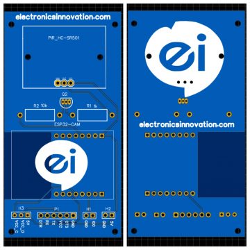
PCB Designing:
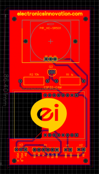
Below is the PCB for the above schematic, I have Placed all the components on the Top layer, All annotation are placed on the Top Layer, and Finally I have added our website logo on the Both Top Silk Layer & Bottom Silk layer.
PCB Order:
Below is the Expected Realtime PCB Picture. Download the Gerber file to a known location and Order the PCB on PCBway.com by uploading the Gerber file.
Note: I have clearly explained the process of Downloading the Gerber file and Ordering the PCB on PCBWay.com. You can refer to the video if you don’t know.
Unboxing PCB:
It took me, 7 days to get my parcel delivered to my lab from PCBway via DHL Courier Service. PCBs are nicely packed in the cardboard box.

Inside the cardboard box, PCBs are neatly packed in the Vacuum Plastic film packaging. PCBs are so nice, I can feel the softness of the surface of the PCBs when I touch them. Soldering mask and the Silkscreen of the PCBs are very good at quality. The border finishing added value to the PCBs.

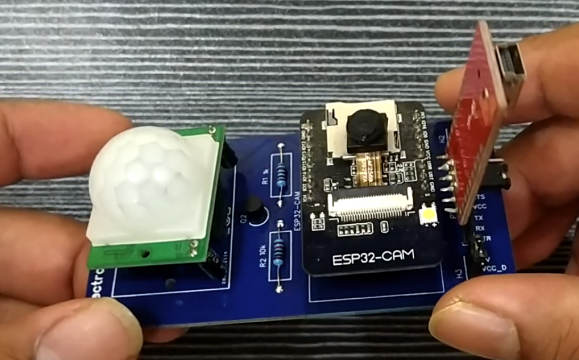
PCB Assembly:
I have soldered all the components on the PCB, I have followed the standard assembling process. after 10 mins of soldering all the components sits in their respective places. After Placing all the components, It will be something like this.
Setting up Telegram bot:
I have clearly explained this process on the video tutorial, You can refer to that for better understanding.
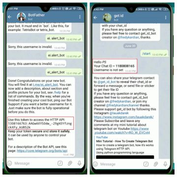
Step1: Open Telegram and search for Bot father. Click on start. then send a message “/newbot”
Step2: It will ask you name for the bot, Simply Give a name for your bot, I named my bot as “ei.alert”
Step3: Again It will ask you the username for the bot, Enter the username for the bot, I give it as “ei_alert_bot” Ater entering a username, you will get the token, That’s it, click on the token and it will be automatically copied to clipboard then save it for future use.
Note: make sure that the username has to be unique, it should end with “bot” and there will be no empty spaces or dots because it will consider as an invalid username.
Step4: Come back to the main page of Telegram, and search for the bot with full name. In my case it is “ei.alert”, then start it.
Step5: Now, again come back to the main page of Telegram, and search for “get id bot”, and start it. within a few seconds, you will receive Chat ID. Save this chat ID along with Token. That’s it, we have successfully set up the Telegram to receive the notifications.
I have marked both Telegram Bot token and UsesID in the below screenshot for your reference.
Installing ESP32 Add-on, Programming part.
We’ll program the ESP32 using Arduino IDE. So, we should have the esp32 addon installed in our Arduino Ide.
1. ESP32 add-on Arduino IDE.
In this example, we use the Arduino IDE to program the ESP32-Cam board. So, we need to have Arduino IDE installed as well as the ESP32 add-on. If you haven’t installed the ESP32 add-on in your machine, follow the below tutorials and get it installed.
2. Source Code: Motion triggered Telegram Alert device with help of ESP32 camera
Here Is the code for Motion triggered Telegram Alert device with ESP32 camera, Copy this code and paste it into the Arduino IDE. but do not upload the code yet. we need to make some changes in the code to work for you.
#include <WiFi.h>
#include <WiFiClientSecure.h>
#include "soc/soc.h"
#include "soc/rtc_cntl_reg.h"
#include "esp_camera.h"

// Enter your WiFi ssid and password
const char* ssid     = "XXXXXXXXXXXXXXXXX";   //WIFI SSID
const char* password = "XXXXXXX";   //WIFI password
String token = "Enter Telegram bot token";
String chat_id = "Enter Chat ID";

//CAMERA_MODEL_AI_THINKER
#define PWDN_GPIO_NUM     32
#define RESET_GPIO_NUM    -1
#define XCLK_GPIO_NUM      0
#define SIOD_GPIO_NUM     26
#define SIOC_GPIO_NUM     27
#define Y9_GPIO_NUM       35
#define Y8_GPIO_NUM       34
#define Y7_GPIO_NUM       39
#define Y6_GPIO_NUM       36
#define Y5_GPIO_NUM       21
#define Y4_GPIO_NUM       19
#define Y3_GPIO_NUM       18
#define Y2_GPIO_NUM        5
#define VSYNC_GPIO_NUM    25
#define HREF_GPIO_NUM     23
#define PCLK_GPIO_NUM     22

int gpioPIR = 13;   //PIR Motion Sensor

void setup()
{
  WRITE_PERI_REG(RTC_CNTL_BROWN_OUT_REG, 0);

  Serial.begin(115200);
  delay(10);
  WiFi.mode(WIFI_STA);
  Serial.println("");
  Serial.print("Connecting to ");
  Serial.println(ssid);
  WiFi.begin(ssid, password);
  long int StartTime=millis();
  while (WiFi.status() != WL_CONNECTED)
  {
    delay(500);
    if ((StartTime+10000) < millis()) break;
  }

  Serial.println("");
  Serial.println("STAIP address: ");
  Serial.println(WiFi.localIP());
  Serial.println("");

  if (WiFi.status() != WL_CONNECTED) {
    Serial.println("Reset");

    ledcAttachPin(4, 3);
    ledcSetup(3, 5000, 8);
    ledcWrite(3,10);
    delay(200);
    ledcWrite(3,0);
    delay(200);
    ledcDetachPin(3);
    delay(1000);
    ESP.restart();
  }
  else
  {
    ledcAttachPin(4, 3);
    ledcSetup(3, 5000, 8);
    for (int i=0;i<5;i++) {
      ledcWrite(3,10);
      delay(200);
      ledcWrite(3,0);
      delay(200);
    }
    ledcDetachPin(3);
  }

  camera_config_t config;
  config.ledc_channel = LEDC_CHANNEL_0;
  config.ledc_timer = LEDC_TIMER_0;
  config.pin_d0 = Y2_GPIO_NUM;
  config.pin_d1 = Y3_GPIO_NUM;
  config.pin_d2 = Y4_GPIO_NUM;
  config.pin_d3 = Y5_GPIO_NUM;
  config.pin_d4 = Y6_GPIO_NUM;
  config.pin_d5 = Y7_GPIO_NUM;
  config.pin_d6 = Y8_GPIO_NUM;
  config.pin_d7 = Y9_GPIO_NUM;
  config.pin_xclk = XCLK_GPIO_NUM;
  config.pin_pclk = PCLK_GPIO_NUM;
  config.pin_vsync = VSYNC_GPIO_NUM;
  config.pin_href = HREF_GPIO_NUM;
  config.pin_sscb_sda = SIOD_GPIO_NUM;
  config.pin_sscb_scl = SIOC_GPIO_NUM;
  config.pin_pwdn = PWDN_GPIO_NUM;
  config.pin_reset = RESET_GPIO_NUM;
  config.xclk_freq_hz = 20000000;
  config.pixel_format = PIXFORMAT_JPEG;

  if(psramFound())
{
    config.frame_size = FRAMESIZE_VGA;
    config.jpeg_quality = 10;  //0-63 lower number means higher quality
    config.fb_count = 2;
  }
else
{
    config.frame_size = FRAMESIZE_QQVGA;
    config.jpeg_quality = 12;  //0-63 lower number means higher quality
    config.fb_count = 1;
  }

  // camera init
  esp_err_t err = esp_camera_init(&config);
  if (err != ESP_OK)
{
    Serial.printf("Camera init failed with error 0x%x", err);
    delay(1000);
    ESP.restart();
  }

sensor_t * s = esp_camera_sensor_get();
 s->set_framesize(s, FRAMESIZE_XGA);

}

void loop()
{

  pinMode(gpioPIR, INPUT_PULLUP);
  int v = digitalRead(gpioPIR);
  Serial.println(v);
  if (v==0)
  {
    alerts2Telegram(token, chat_id);
    delay(10000);
  }
  delay(1000);

}

String alerts2Telegram(String token, String chat_id)
{
  const char* myDomain = "api.telegram.org";
  String getAll="", getBody = "";

  camera_fb_t * fb = NULL;
  fb = esp_camera_fb_get();
  if(!fb)
{
    Serial.println("Camera capture failed");
    delay(1000);
    ESP.restart();
    return "Camera capture failed";
  }


WiFiClientSecure client_tcp;

  if (client_tcp.connect(myDomain, 443))
{
    Serial.println("Connected to " + String(myDomain));

    String head = "--India\r\nContent-Disposition: form-data; name=\"chat_id\"; \r\n\r\n" + chat_id + "\r\n--India\r\nContent-Disposition: form-data; name=\"photo\"; filename=\"esp32-cam.jpg\"\r\nContent-Type: image/jpeg\r\n\r\n";
    String tail = "\r\n--India--\r\n";

    uint16_t imageLen = fb->len;
    uint16_t extraLen = head.length() + tail.length();
    uint16_t totalLen = imageLen + extraLen;

    client_tcp.println("POST /bot"+token+"/sendPhoto HTTP/1.1");
    client_tcp.println("Host: " + String(myDomain));
    client_tcp.println("Content-Length: " + String(totalLen));
    client_tcp.println("Content-Type: multipart/form-data; boundary=India");
    client_tcp.println();
    client_tcp.print(head);

    uint8_t *fbBuf = fb->buf;
    size_t fbLen = fb->len;


    for (size_t n=0;n<fbLen;n=n+1024)
 {

      if (n+1024<fbLen)
{
        client_tcp.write(fbBuf, 1024);
        fbBuf += 1024;
      }
      else if (fbLen%1024>0)
{
        size_t remainder = fbLen%1024;
        client_tcp.write(fbBuf, remainder);
      }
    }

    client_tcp.print(tail);

    esp_camera_fb_return(fb);

    int waitTime = 10000;   // timeout 10 seconds
    long startTime = millis();
    boolean state = false;

    while ((startTime + waitTime) > millis())
    {
      Serial.print(".");
      delay(100);
      while (client_tcp.available())
      {
          char c = client_tcp.read();
          if (c == '\n')
          {
            if (getAll.length()==0) state=true;
            getAll = "";
          }
          else if (c != '\r')
            getAll += String(c);
          if (state==true) getBody += String(c);
          startTime = millis();
       }
       if (getBody.length()>0) break;
    }
    client_tcp.stop();
    Serial.println(getBody);
  }
  else {
    getBody = "Connection to telegram failed.";
    Serial.println("Connection to telegram failed.");
  }

  return getBody;
}
The following should change before you upload the code:
Network Credentials:
Insert your network credentials in the following lines:
// Enter your WiFi ssid and password
const char* ssid     = "XXXXXXXXXXXXXXXXX";   //WIFI SSID
const char* password = "XXXXXXX";   //WIFI password
Telegram Credentials:
Insert Telegram credentials Token & ChatID in the following lines:
String token = "Enter Telegram bot token";
String chat_id = "Enter Chat ID";
Uploading Source Code:
Connect FTDI Module with Computer with help of data cable as shown in the below picture and restart the ESP32 camera module.
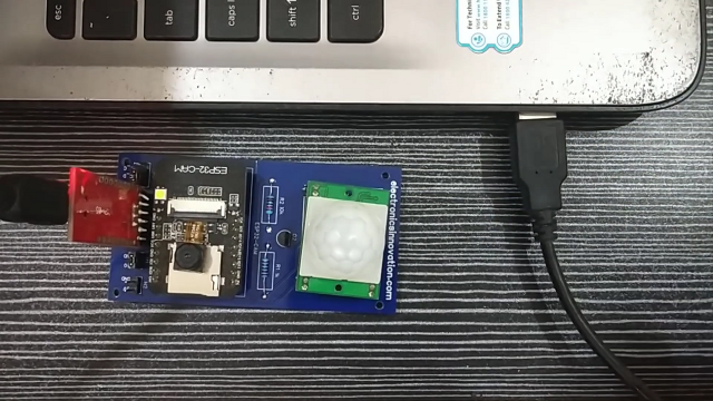
Note: Make sure you have connected IO0 and GND pins to put the ESP32-Cam module in Flash/ Boot mode.
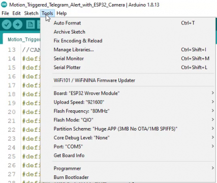
Check the Uploading configurations like board: ESP32 Wroover Module, Uploading Speed, and select the right port. If everything okay, upload it.
Testing & Demonstration:
After successful uploading, disconnect IO0 and GND pins then, Open Serial Monitor. On the Serial monitor, you can see our ESP32 successfully connected to the programmed wifi and allocated with IP address. As soon as the motion detected, GPIO13 gets LOW, then ESP32 connected to Telegram API, and sent the captured Image. you can see the received picture on the telegram mobile screen. 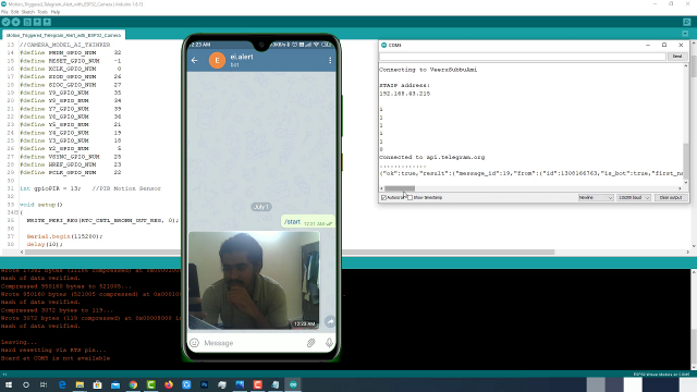
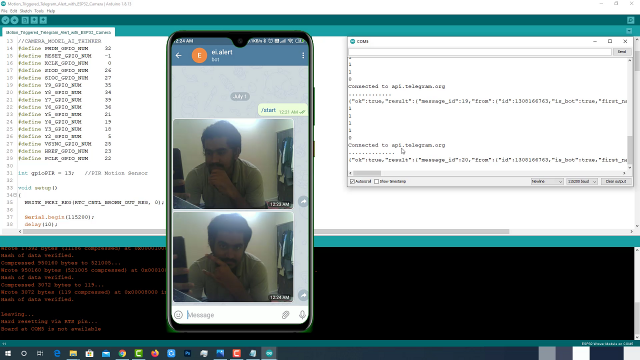
Let’s try once more. yeah, again we have received a captured picture on the Telegram. Haha, Some How I managed to give a good pose but I failed.
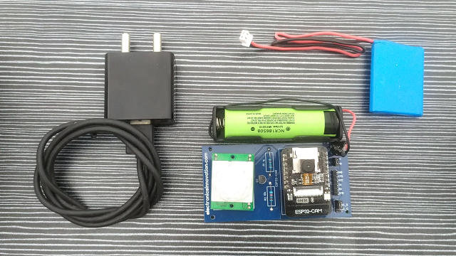
Power Source:
As I have discussed in the previous video, you can use any 5v 1A Adapter or 3.7v batteries like Li-ion or Li-po batteries which can be connected as shown below.
Summary:
That’s it, our Motion triggered Telegram Alert device is ready. You can install this at any surveillance area, It will simply capture an image and send it to your telegram if any human motion is detected.
Video Tutorial: Motion Triggered Telegram Alert
Thank you for sharing your work I think I will make the project with your code, but I was wondering if I am out and about shopping will my phone still receive the Telegram to let me know that motion has been detected or only when I am near my router.
Thanks
Hello
Telegram App is blocked my area and i am using it via MTProto proxy, How can esp32-cam communicate with Telegram server via MTProto proxy?
sussuse fully done the job but serial monitor says telegram not connected
Welcome!
How can I enter a static IP?
I am unable to program. It shows the error LedcAttachPoint (3, 4) not declared