Table of Contents:
Introduction:
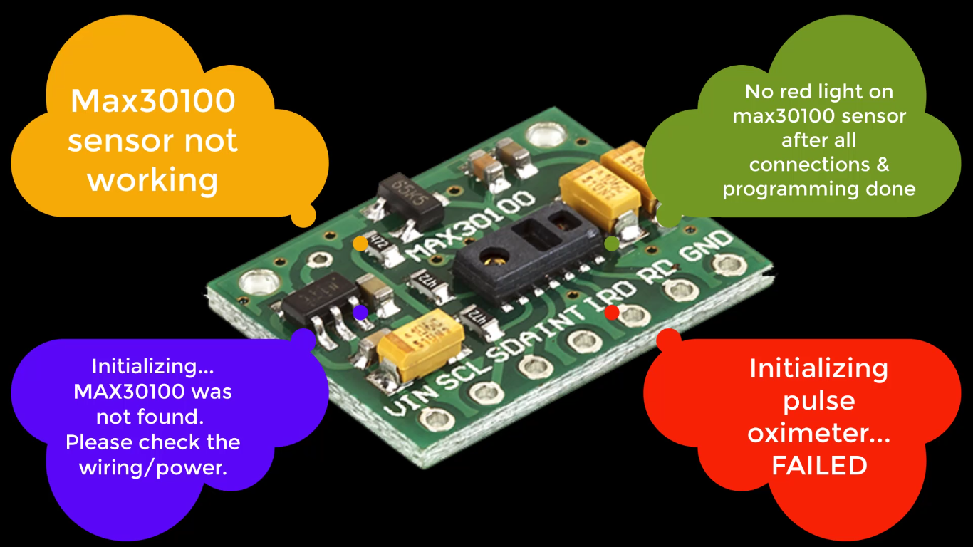
Max30100 sensor not working (or) no red light on max30100 sensor after all connections & programming done
if you are having a similar question in your mind or
” Initializing pulse oximeter…FAILED” (or) “Initializing… MAX30100 was not found. Please check the wiring/power”
if your serial monitor showing similar output and you are looking for the solution for these issues, then you have stumbled at the right place. this video will help you to solve all these issues.
So, take a deep breath and sit back and relax, we are going to solve all these issues in few minutes.
PCBWay:
PCBWay is one of the best PCB manufacturers in the current industry.
PCBWay is offering services like PCB prototype, SMD Stencil, PCB assembly, Flexible PCBs & Advanced PCBs.
At PCBWay.com we can get 10 pieces of 2 layered PCBs at just $5 with 24 hours build time.
The Best part of PCBWay is the Instant quote feature, just enter the PCB size, choose the quantity, layers, and thickness. That’s it, we will get the instant quote. place an order by clicking on saving to cart.

Now, let’s dive into the episode.
Video Tutorial:
This tutorial is also available in video format, you can watch the below videos or continue reading this article.
The Problem:
Straight to the point, this problem with hardware only. there might be no problem with code or connections,
I’m sure you have already reverified the connection twice and tried with different examples of code. but no use.
Let’s take a closer look at the schematic diagram if we can figure out the issue.
This is the schematic diagram of the Pulse Oximeter sensor.
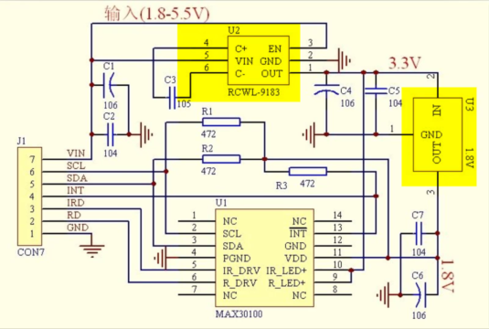
As you can see here there are 2 voltage regulators, this will give a constant output of 3.3v, where input can be anything from 1.8 to 5.5v.
Coming to the second regulator, it will give a constant 1.8v output when the input is 3.3v.This regulator is used to power up the max30100 sensing module which required only 1.8v. Up to here, everything is perfect.
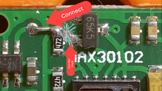
The main problem is, with the below-highlighted connection only. as you can see here, there are 3 pull-up resistors. but they are connected to 1.8v to make it pull up. the problem is, our microcontrollers are 3.3v based; so, these pullup resistors are not making SDA and SCL data lines neither pull-up nor pull down.
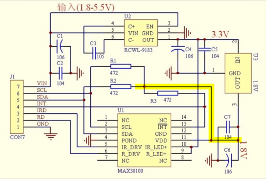
because of this connection, the data which is sending from the sensor to the microcontroller being corrupted and we are getting error responses as ” Initializing pulse oximeter…FAILED” (or) “Initializing… MAX30100 was not found. Please check the wiring/power”
Since the sensor can’t communicate with the microcontroller, this will never receive a command to read the pulse and oxygen level, thus the red LED will never glow.
Now, we understood the real problem, what should be the solution for this???
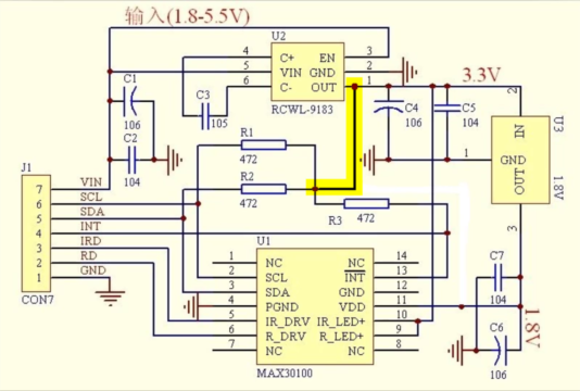
well, the solution is very simple. we just need to connect these pull-up resistors to the 3.3v network. that’s it, that simple it is. but how to connect it or where to connect matters.
There are 2 ways to do it.
- Cut this line and connect this pull-up resistor with the 3.3v pin of this regulator. you don’t have to connect all resistors. because all three resistors are internally connected on the PCB as shown here.
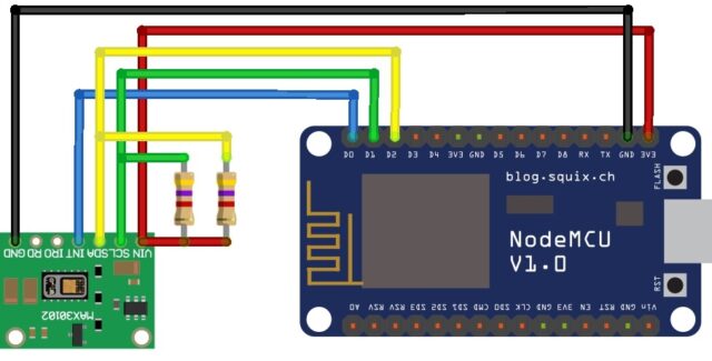
- Simply remove these 3 resistors and connect an external 4.7kilo ohm resistors on the breadboard. you don’t have to cut the PCB line here. add 2 pull-up resistors to the SDA and SCL data lines of the sensors as shown in the circuit diagram.
After all connections, the circuit might be something like this.
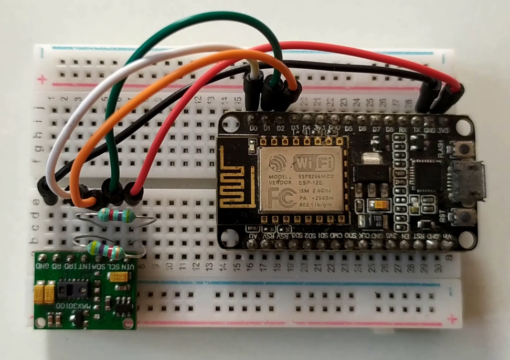
choose your feasible way and do it.
After successfully completing any of the ways, you can connect to any microcontroller and test it.
I’m sure, it will work perfectly as shown here, if you followed the right way.
SourceCode:
You can use this code to program your microcontroller (Arduino, ESP32, ESP8266 )using Arduino IDE.
#include <Wire.h>
#include "MAX30100_PulseOximeter.h"

#define REPORTING_PERIOD_MS     1000

// PulseOximeter is the higher level interface to the sensor
// it offers:
//  * beat detection reporting
//  * heart rate calculation
//  * SpO2 (oxidation level) calculation
PulseOximeter pox;

uint32_t tsLastReport = 0;

// Callback (registered below) fired when a pulse is detected
void onBeatDetected()
{
  Serial.println("Beat!");
}

void setup()
{
  Serial.begin(115200);

  Serial.print("Initializing...");

  // Initialize the PulseOximeter instance
  // Failures are generally due to an improper I2C wiring, missing power supply
  // or wrong target chip
  if (!pox.begin()) {
    Serial.println("MAX30100 was not found. Please check the wiring/power.");
    for (;;);
  } else {
    Serial.println("SUCCESS");
  }

  // The default current for the IR LED is 50mA and it could be changed
  //   by uncommenting the following line. Check MAX30100_Registers.h for all the
  //   available options.
  // pox.setIRLedCurrent(MAX30100_LED_CURR_7_6MA);

  // Register a callback for the beat detection
  pox.setOnBeatDetectedCallback(onBeatDetected);
}

void loop()
{
  float HeartRate = 3.0, SpO2 = 3.0;

  // Make sure to call update as fast as possible
  pox.update();
  HeartRate = pox.getHeartRate();
  SpO2 = pox.getSpO2();
  // Asynchronously dump heart rate and oxidation levels to the serial
  // For both, a value of 0 means "invalid"
  if (millis() - tsLastReport > REPORTING_PERIOD_MS) {
    Serial.print("Heart rate:");

    Serial.print(HeartRate);
    Serial.print("bpm / SpO2:");

    Serial.print(SpO2);
    Serial.println("%");

    tsLastReport = millis();
  }
}
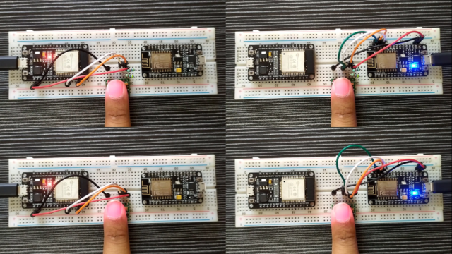
I have followed the both ways with two different sensors & two different microcontrollers (ESP32 & ESP8266)to demonstrate to you,
both sensors are working fine, they are giving accurate, Heartrate and SPO2 data seamlessly as shown here.
Circuit Connection with ESP32 & ESP8266:
Serial monitor output: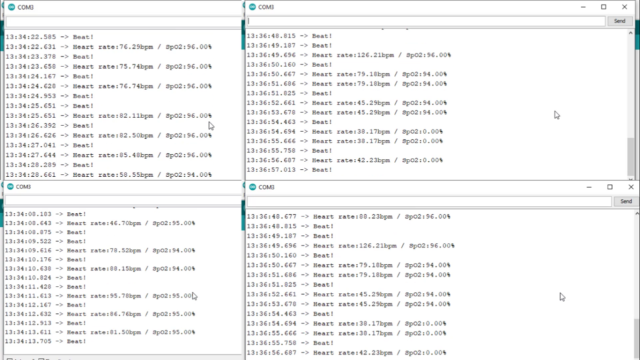
So, that’s all about MAX30100 troubleshooting for you, I hope this video helped you to solve the problem.
stay tuned to electronics innovation for more interesting projects and trouble shooting videos.
If you are facing any other issues, just draft a mail to askus.electronicsinnovation@gmail.com
we try to help you as soon as possible.
See you on the next interesting episode, bubyeee…
[…] Here is the circuit diagram for the IoT-based Covid Patient Blood Oxygen monitor with ESP32. Connect the MAX30100 Sensor module with ESP32 and add 2 pull-up resistors to the SDA and SCL data lines of the sensors as shown in the circuit diagram. if you want to know, why do we need to solder external pull-up resistors? follow this tutorial. […]
[…] Here Is the circuit diagram to interface Max30100 and OLED display with ESP32, Since we are using the I2C protocol, both modules can be interfaced with ESP32 with the same Pins. if you want to know, why do we need to solder external pull-up resistors? follow this tutorial. […]
Sir
I tried the second method
But oximeter sensor still not working
What to do sir
Sir getting only 0 readings in max 30100 sensor. What to do sir?
[…] Here Is the circuit diagram to interface Max30100 and OLED display with ESP32, Since we are using the I2C protocol, both modules can be interfaced with ESP32 with the same Pins. if you want to know, why do we need to solder external pull-up resistors? follow this tutorial. […]
Hi, is the same if I use MAX30100? I saw the board that you used in this tutorial is MAX30102.
I tried the second method, but it still says failed to initialise pulse oximeter. Kindly help out with this problem, a lot of people are facing the same issue
[…] To learn in deep about this problem , you can visit – https://electronicsinnovation.com/solved-max30100-not-working-initializing-pulse-oximeter-failed/ […]