Table of Contents:
Overview:
In the previous video, we have set up this LPS8 gateway and register the same on The Things Network. We have also seen that the gateway successfully connected to the network server and transmitted its status message.
We have also explored that what are the event details included in that status message.
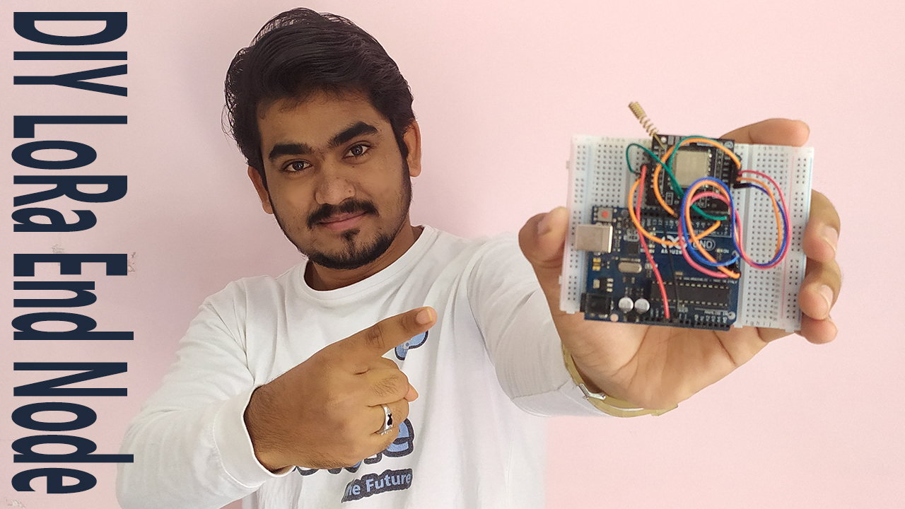
In this video, we are going to develop a Lora end node that can be activated in ABP mode with RFM95 module and Arduino UNO to publish a “hello electronics innovation world!” message. as we have discussed earlier the data being transmitted over the LoRaWAN is encrypted, so we will also see how to decrypt that data and see what is the exact data present in that data packet.
So, Let’s see how we can do that.
Video Tutorial: How to make LoRa Node?
Required components:
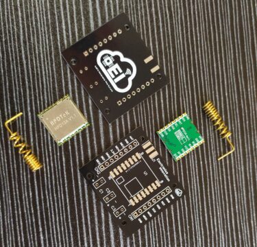
- RFM95 modules along with Breadboard friendly PCB breakout boards – 1
- Arduino Uno
- Breadboard
- Connecting wires
Making RFM95 Lora transceiver PCBWay.com
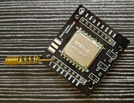
This RFM95 LoRa transceiver module does not breadboard friendly, which means we cannot solder these 2.54mm male headers to it, or we can place it neither breadboard nor Vero boards. So, I have designed a PCB to make it breadboard-friendly. We can extend the SMD pads of RFM95 with Male headers as shown here. So, that we can place it on both Breadboard and Vero board.
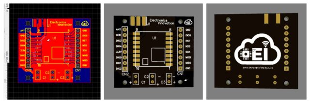
The PCB looks something like that below. The RFM95 module can be soldered on SMD pads. In 3D view PCB looking gorgeous right.
I have generated Gerber files and saved them into the available folder.
PCBWay:
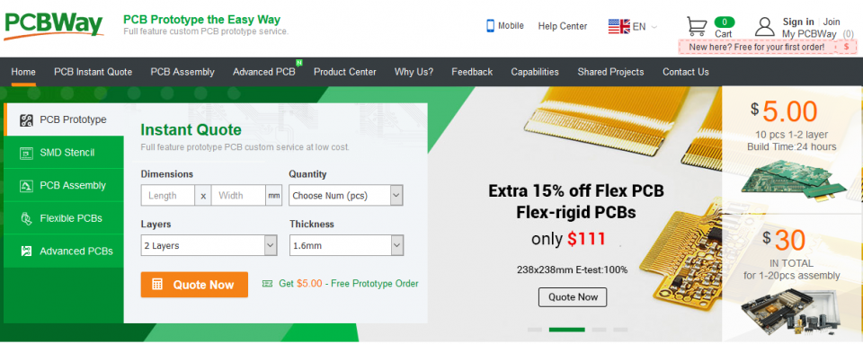
I have ordered the PCB on PCBway.com, PCBway.com is an online printed circuit board manufacturing enterprise that turns your DIY breadboard circuits into professional PCBs at just 5 dollars.
PCBWay.com offers all services you need to make Hardware for your IoT or Embedded Devices.
If you have a similar requirement, do check out their website for more details using this link.
Later I have soldered the RFM95 module on the received PCB boards. I have clearly explained this process here. If you wish to have a look check it.
Application Registration:
Visit The Things Network Platform, If you are a first-time user, Signup by providing all required details. Then log in to the platform using the same credentials. Then come to the Home.
Click on the username and select console.
Here we have two options create an application and register a gateway, choose to create an application.
The owner will be selected default, if you want you can change from here. Enter Application ID, this can be an alphanumeric string but only lower case alphabets are allowed, Then enter Application name, this can be anything. Uppercase alphabets are allowed here. If you want you can also add a description for the application here.
Then click on create an application. That’s it, a new application has been created.

In this application, we can add our END devices. If you have a ready-made device from any certified manufacturer, you can add that device in the section “from the LoRaWAN device repository”, but we are developing our device, so that can be added to the manual category.
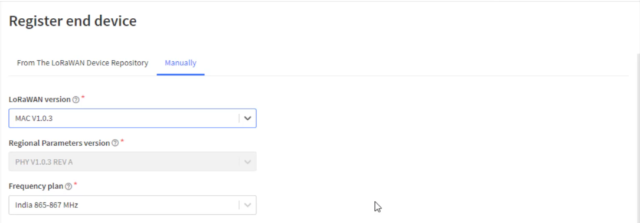
Select the LoRaWAN version, we have to specify which version on the LoRaWAN our device is using. select MAC1.0.3 then select the operating frequency.
865-867Mhz selected, as I am from India.
Here you have to observe one thing if you are from India. the frequency plan 865-867Mhz is available on the MAC1.0.3 or later version only. You will not find the 865-867Mhz frequency band on MAC1.0.2 or the lower version.
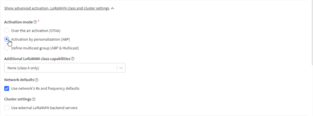
Click on show advanced activation loraan class and cluster settings, Select the activation Mode, Either it is OTAA – Over the air activation or ABP – Activation by personalization in our case it is ABP.
Leave the rest of the settings default and click on generate DevEUI, Device Address, App session Key, and Network session key. We have to configure our End node with newly generated credentials.
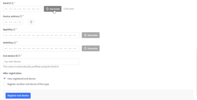
Then click on the register end device. That’s it. The device has been created successfully.
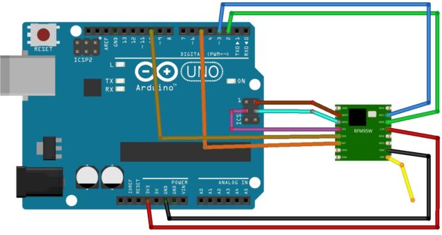
Circuit Diagram:
Interface Arduino Uno with RFM95 module as shown in the circuit below.
Programming:
Visit this git hub page and download the Arduino-lmic library and then install it using the add zip library feature in the Arduino. After successful installation, you can find the library in the include library section with the name, IBM LMIC Framework.
Now go to the examples from the file menu and search for the IBM LMIC framework and then open the ttn-abp example.

Before uploading code to the node, we have to make some changes to work according to our frequency band and registration on ttn. We have to add network session key, appskey, devaddr here. all the credentials can be found on the ttn. also, we need to make changes to a couple of library files.
I have clearly explained what are the changes needed to be done before uploading the sketch to the Arduino. I recommend you watch the video and continue the process.
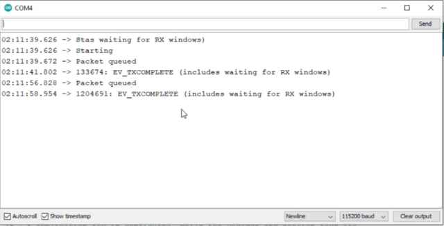
Once all modifications are done successfully, connect Arduino UNO with the laptop, select the board Arduino Uno, and port. then click on upload. after successful uploading open serial port with baud rate 115200,
if you see the EV-TXCOMPLETE text on the serial monitor, congratulations. your Lora device is transmitting the Lora data packets.
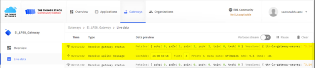
Open ttn, go to gateway live data, as you can see here gateway received an uplink from the device 26 0B 50 1B,
Now go to applications live data.
we have also received the payload from the device. total of 3 data packets we can see here. we can also see the spreading factor signal to noise ratio, RSSI of the received data packet.
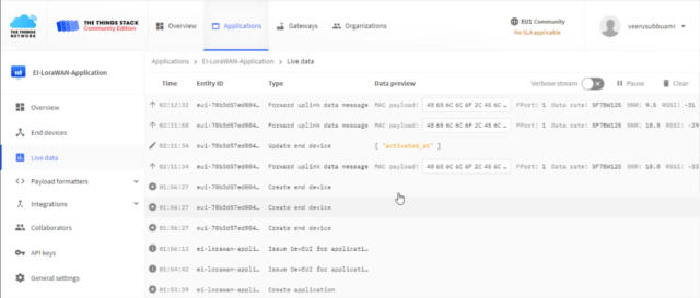
but the payload is not readable. we have sent a hello electronics innovation world message. but here we are receiving some random data. what could be the problem??? Is there any malfunctioning happened to data??? do you have any idea, why it is happening??
.
.
.
yes… you are right. The data which is being transmitted over the LoRaWAN is encrypted. Here we are looking at the hexadecimal format of encrypted messages. now we need to decrypt or convert that message to a human-readable format.
to decrypt the message, go to end nodes, click on the end node, go to payload formats, choose formatter type javascript, and past this code.
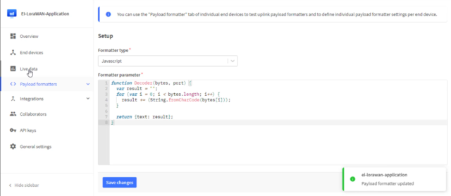
function Decoder(bytes, port) {
  var result = "";
  for (var i = 0; i < bytes.length; i++) {
    result += (String.fromCharCode(bytes[i]));
  }

  return {text: result};
}
now come back to the ttn application live data and reload the page. as you can see here, we can see the data inside the data packet.
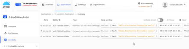
So, this is how we can decrypt the data of the lorawan data packets. as the data is transferred in the encrypted format, the security will be very high for the data transmission.
That’s it for this tutorial. we have successfully developed a Lora end node that can be activated in ABP mode with RFM95 module and Arduino UNO to publish a “Hello electronics innovation world!” message. aslo we have successfully decrypted the Lorawan data packets.
Stay tuned to electronicsinnovation.com for the more interesting project on lorawan communications.
[…] Now We have to Develop a LoRa End Node with RFM95 module and Arduino, but due to the long length of the article, I have decided to write another article for that. you can find that article here. […]
[…] format. I have already done this decryption process for this application in the previous article, that’s why the data is automatically decrypted and converted to human-readable […]