Table of Contents:
Introduction: Smart Patient Blood Oxygen monitor
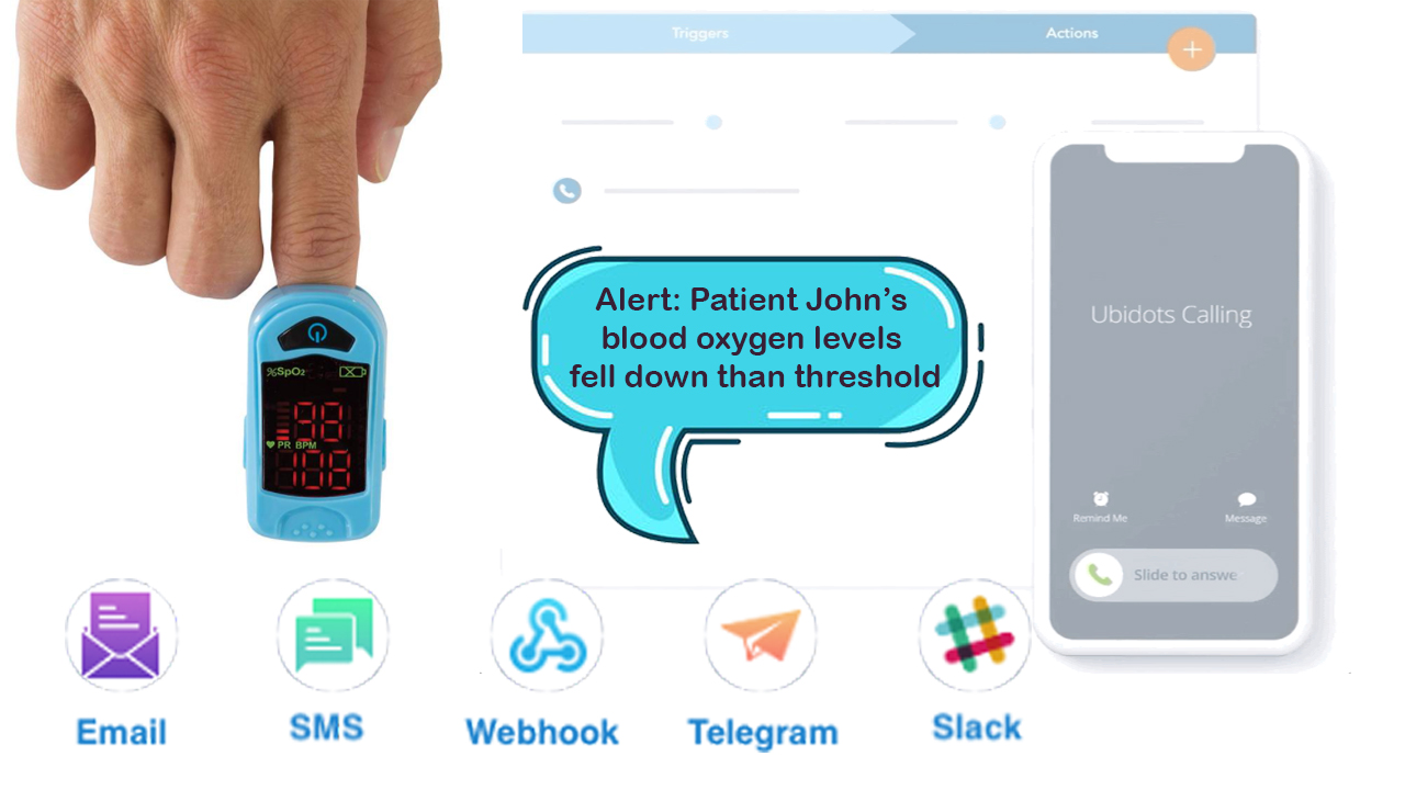
In this article”Smart Patient Blood Oxygen monitor”, we are going to talk all about “IoT based Smart Patient Blood Oxygen monitor with ESP8266 and sending critical alerts to the hospital management and patient loved ones” This project is truly designed for patients whose blood oxygen levels need to be monitored 24×7, for example, covid patients or any other patients who are on the ventilator. This project continuously monitors the blood oxygen levels and logs them to the ubidots IoT platform. also, it will send critical medical alerts like voice calls, SMS, EMail, and telegram message to the Hospital management and patient loved ones with the help of Ubidots events and alerts features.
I am so excited about this project. so, without wasting much time let’s dive into the episode.
Before jumping into the episode, let me thank my favorite PCB manufacturer “PCBWay.com” for sponsoring this project.
PCBWay:
PCBWay is one of the best PCB manufacturers in the current industry.
PCBWay is offering services like PCB prototype, SMD Stencil, PCB assembly, Flexible PCBs & Advanced PCBs.
At PCBWay.com we can get 10 pieces of 2 layered PCBs at just $5 with 24 hours build time.
The Best part of PCBWay is the Instant quote feature, just enter the PCB size, choose the quantity, layers, and thickness. That’s it, we will get the instant quote. place an order by clicking on saving to cart.

Video Tutorial: Part 1 Smart Patient Blood Oxygen monitor
This tutorial is also available in video format, you can watch the below videos or continue reading this article.
Required Components:
1. Breadboard (Buy from Amazon)
2. ESP8266 Module (Buy from Amazon)
3. MAX30100 pulse oximeter sensor (Buy from Amazon)
4. 4.7k ohm resistors (Buy from Amazon)
5. Connecting wires. (Buy from Amazon)
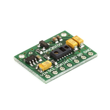
Overview: Pulse Oximeter and Heart-Rate Sensor (MAX30100)
Sensor Description:
The MAX30100 is complete pulse oximetry and heart-rate sensor system solution designed for the demanding requirements of wearable devices. The MAX30100 pro-vides very small total solution size without sacrificing optical or electrical performance. Minimal external hardware components are needed for integration into a wearable device. The MAX30100 is fully configurable through software registers, and the digital output data is stored in a 16-deep FIFO within the device. The FIFO allows the MAX30100 to be connected to a microcontroller or microprocessor on a shared bus, where the data is not being read continuously from the device’s registers.
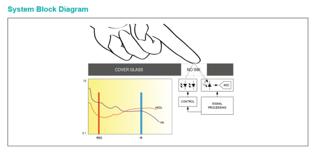
SpO2 Subsystem
The SpO2 subsystem in the MAX30100 is composed of ambient light cancellation (ALC), 16-bit sigma-delta ADC, and a proprietary discrete-time filter. The SpO2 ADC is a continuous-time oversampling sigma-delta converter with up to 16-bit resolution. The ADC output data rate can be programmed from 50Hz to 1kHz. The MAX30100 includes a proprietary discrete-time filter to reject 50Hz/60Hz interference and low-frequency residual ambient noise
Temperature Sensor
The MAX30100 has an on-chip temperature sensor for (optionally) calibrating the temperature dependence of the SpO2 subsystem. The SpO2 algorithm is relatively insensitive to the wavelength of the IR LED, but the red LED’s wavelength is critical to correct interpretation of the data. The temperature sensor data can be used to compensate for the SpO2 error with ambient temperature changes.
LED Driver
The MAX30100 integrates red and IR LED drivers to drive LED pulses for SpO2 and HR measurements. The LED current can be programmed from 0mA to 50mA (typical only) with proper supply voltage. The LED pulse width can be programmed from 200μs to 1.6ms to optimize measurement accuracy and power consumption based on use cases
Benefits and Features
●Complete Pulse Oximeter and Heart-Rate Sensor Solution Simplifies Design
• Integrated LEDs, Photo Sensor, and High-Performance Analog Front -End
• Tiny 5.6mm x 2.8mm x 1.2mm 14-Pin Optically Enhanced System-in-Package
●Ultra-Low-Power Operation Increases Battery Life for Wearable Devices
• Programmable Sample Rate and LED Current for Power Savings
• Ultra-Low Shutdown Current (0.7μA, typ)
●Advanced Functionality Improves Measurement Performance
• High SNR Provides Robust Motion Artifact Resilience
• Integrated Ambient Light Cancellation
• High Sample Rate Capability• Fast Data Output Capability
Applications
●Wearable Devices
●Fitness Assistant Devices
●Medical Monitoring Devices
Circuit Diagram: Smart Patient Blood Oxygen monitor
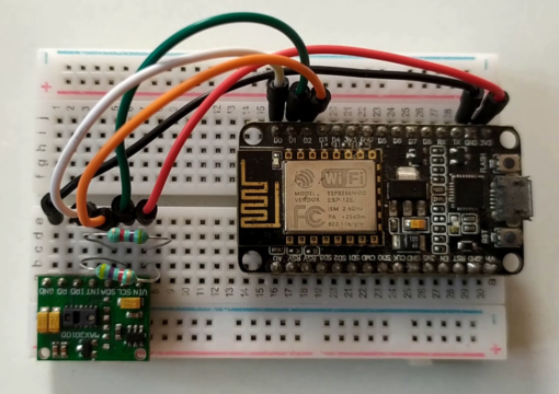
Here is the circuit diagram for the IoT-based Smart Patient Blood Oxygen meter with ESP8266. Connect the MAX30100 Sensor module with ESP8266 and add 2 pull-up resistors to the SDA and SCL data lines of the sensors as shown in the circuit diagram.
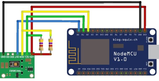
After all connections, the circuit might be something like this.
Creating device in Ubidots:
Before jump into the programming, part let’s create a device in the Ubidots Platform for our solution. follow the below steps.
- Visit ubidots.com,
- Go to Dashboard,
- Click on devices,
- create a new device, select a blank device,
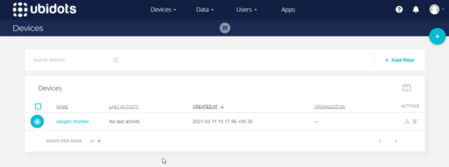
- Enter the name for the device then click on this green tickmark to create the device.
That’s it the device is successfully created.
Programming part: Smart Patient Blood Oxygen monitor
Coming to the programming part, Here Is the code for the IoT-based Smart Patient Blood Oxygen meter with ESP8266. We need to provide the below details, to make this code work with your Ubidots device.
WiFi Credentials:
Provide WiFi SSID and password for Internet Connection.
#define WIFISSID “XXXXXXXXXXXXXXXXX” // Put your WifiSSID here
#define PASSWORD “XXXXXXXXXXXXX” // Put your wifi password here
Ubidots Credentials:
Provide Ubidots token, we can get this from the Ubidots itself. Go to API Credentials. Copy the token and past it over here
Enter MQTT Client name, This can be any alphanumeric string.
Then enter the Variable label & Device label, which we have created on Ubidots earlier.
#define TOKEN “XXXXXXXXXXXXXXXXXXXXXXXXXXXXXXXXXXXXX” // Put your Ubidots’ TOKEN
#define DEVICE_LABEL “XXXXXXXXXXXXXXX” // Put the device label
#define VARIABLE_LABEL_1 “heartrate” // Put the variable label
#define VARIABLE_LABEL_2 “SPo2” // Put the variable label
#define MQTT_CLIENT_NAME “EI_OXMO” // MQTT client Name, put a Random ASCII
Source code: Smart Patient Blood Oxygen monitor
#include <PubSubClient.h>
#include <ESP8266WiFi.h>
#include <ESP8266WiFiMulti.h>
#include <stdio.h>

#include <Wire.h>
#include "MAX30100_PulseOximeter.h"

#define REPORTING_PERIOD_MS     1000
#define WIFISSID "XXXXXXXXXXXXXXXXX" // Put your WifiSSID here
#define PASSWORD "XXXXXXXXXXXXX" // Put your wifi password here
#define TOKEN "XXXXXXXXXXXXXXXXXXXXXXXXXXXXXXXXXXXXX" // Put your Ubidots' TOKEN
#define DEVICE_LABEL "XXXXXXXXXXXXXXX" // Put the device label
#define VARIABLE_LABEL_1 "heartrate" // Put the variable label
#define VARIABLE_LABEL_2 "SPo2" // Put the variable label
#define MQTT_CLIENT_NAME "EI_OXMO" // MQTT client Name, put a Random ASCII

PulseOximeter pox;
uint32_t tsLastReport = 0;

char mqttBroker[] = "industrial.api.ubidots.com";
char payload[700];
char topic[150];

// Space to store values to send
char str_val_1[6];
char str_val_2[6];

int flag = 0;

ESP8266WiFiMulti WiFiMulti;
WiFiClient ubidots;
PubSubClient client(ubidots);

void onBeatDetected()
{
  ;
}

void callback(char* topic, byte* payload, unsigned int length) {
  Serial.print("Message arrived [");
  Serial.print(topic);
  Serial.print("] ");
  for (int i = 0; i < length; i++) {
    Serial.print((char)payload[i]);
  }
  Serial.println();
}

void reconnect() {
  // Loop until we're reconnected
  while (!client.connected()) {
    Serial.println("Attempting MQTT connection...");

    // Attempt to connect
    if (client.connect(MQTT_CLIENT_NAME, TOKEN, "")) {
      Serial.println("connected");
    } else {
      Serial.print("failed, rc=");
      Serial.print(client.state());
      Serial.println(" try again in 2 seconds");
      // Wait 2 seconds before retrying
      delay(2000);
    }
  }
}

void setup()
{
  Serial.begin(115200);
  WiFiMulti.addAP(WIFISSID, PASSWORD);
  Serial.println();
  Serial.println();
  Serial.print("Wait for WiFi... ");

  while (WiFiMulti.run() != WL_CONNECTED) {
    Serial.print(".");
    delay(500);
  }

  Serial.println("");
  Serial.println("WiFi connected");
  Serial.println("IP address: ");
  Serial.println(WiFi.localIP());
  client.setServer(mqttBroker, 1883);
  client.setCallback(callback);

  Serial.print("Initializing pulse oximeter..");
  // Initialize the PulseOximeter instance
  // Failures are generally due to an improper I2C wiring, missing power supply
  // or wrong target chip
  if (!pox.begin()) {
    Serial.println("FAILED");
    for (;;);
  } else {
    Serial.println("SUCCESS");
    digitalWrite(1, HIGH);
  }
  pox.setIRLedCurrent(MAX30100_LED_CURR_24MA);

  // Register a callback for the beat detection
  pox.setOnBeatDetectedCallback(onBeatDetected);

}

void loop(){
if (flag == 0)
{
  client.connect(MQTT_CLIENT_NAME, TOKEN, "");
  Serial.println("MQTT connected again");
  flag = 1;
}
  if (!client.connected()) {
    Serial.print("Reconnecting ... ");
    reconnect();
  }
  // Make sure to call update as fast as possible
  pox.update();
  if (millis() - tsLastReport > REPORTING_PERIOD_MS) {


    // to computer Serial Monitor
    Serial.print("BPM: ");
    Serial.print(pox.getHeartRate());
    //blue.println("\n");

    Serial.print("    SpO2: ");
    Serial.print(pox.getSpO2());
    Serial.print("%");
    Serial.println("\n");

    dtostrf(pox.getHeartRate(), 4, 2, str_val_1);
    dtostrf(pox.getSpO2(), 4, 2, str_val_2);

    sprintf(topic, "%s", ""); // Cleans the topic content
    sprintf(topic, "%s%s", "/v1.6/devices/", DEVICE_LABEL);

    sprintf(payload, "%s", ""); // Cleans the payload content
    sprintf(payload, "{\"%s\":", VARIABLE_LABEL_1); // Adds the variable label
    sprintf(payload, "%s {\"value\": %s}", payload, str_val_1); // Adds the value
    sprintf(payload, "%s, \"%s\":", payload, VARIABLE_LABEL_2); // Adds the variable label
    sprintf(payload, "%s {\"value\": %s}", payload, str_val_2); // Adds the value
    sprintf(payload, "%s}", payload); // Closes the dictionary brackets

    Serial.println(payload);
    Serial.println(topic);

    client.publish(topic, payload);
    client.loop();

    tsLastReport = millis();

  }

}
Uploading Source Code:
Connect ESP8266 module with Laptop/computer.
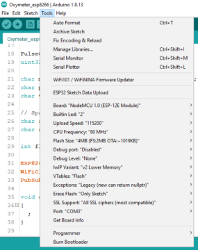
Check the Uploading configurations like board: NodeMCU 1.0 ESP-12E Module, Uploading Speed, and select the right port. If everything is okay Upload it.
While compiling in progress put the ESP8266 in programming mode by press the reset button while holding the Flash button, then release it.
Output: Smart Patient Blood Oxygen monitor
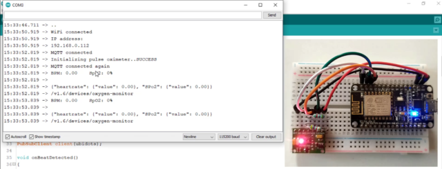
After successful uploading open serial monitor,
On the Serial monitor, we can see our ESP8266 successfully connected to the programmed wifi and allocated with an IP address. Then initiated MQTT connection with Ubidots cloud and connected to it. Then it started publishing Heartrate and percentage of oxygen saturation SPo2 data to the Ubidots platform. gently place your finger on the oximeter, and you can see the live data on the serial monitor. do not press your finger hardly, that will lead to inaccurate data.
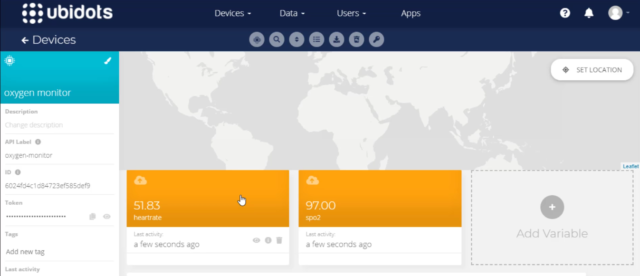
Now, Go to Ubidots and reload it. If you click on the device, you can see the variables and their data.
The best part of the Ubidots is if it receives data from any Module it will automatically create those variables and start storing data for us. here you can see the same variables are created automatically.
Ubidots Data Visualization:
Currently, we are receiving and storing it on the ubidots, let’s visualize the same data. for that Click on Data and then choose Dashboard.
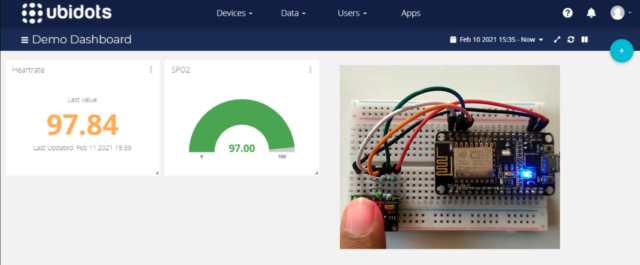
Click on add new widget, you will be prompted with a bunch of data visualization options, choose one among them, I will use a metric to display the Heart rate. Click on add variables, then select the device, and select the variable heart rate, Add a name for the metric. keep the rest of the options default. Later create it.
Now, let’s repeat the same process for SPo2. For spo2 I would like to choose the gauge option to visualize it, Click on add variables, then select the device, and select the variable SPo2, Add a name for the gauge. for Spo2 I would like to add color logic to differentiate the safe or critical blood oxygen levels.
we can add that easily from ubidots, select color logic, add color logic. if the blood oxygen levels are 95% or above they are said to be safe, below 95 % are critical. So, I will put green color if the oxygen levels are greater than 95, and put red color if the oxygen levels are less than 95%. Then click on accept.
After creating you can see the live data in green color on the gauge. because it is greater than 95. if that value is lesser than 95 you can see the red color.
Configuring Critical Medical Alerts using Ubidots Event Function:
Now, let’s move to the most important thing in the episode, Creating alerts when abnormal blood oxygen % is noticed. Ubidots supports integrated events to allow us to send Alerts and notifications to those who need to know when they need to know. so in our case the hospital management and the caretaker of the patient whenever the blood oxygen levels go down. so, let’s configure it now.
Video Tutorial: Part 2 DIY Blood Oxygen monitor
I have clearly explained the configuration of critical medical alerts with the Ubidots Events Engine feature in the below video tutorial, you can watch the below video for better understanding.
Follow the below steps to configure Critical Medical alerts using Ubidots Events Engine.
- Select Events from the Data dropdown.
- Click on the create event button.
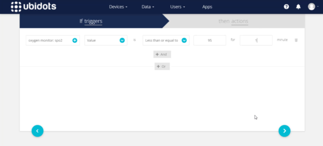
- Select the If triggers tab to organize your event logic.
First, we will create a condition to trigger the event and then call appropriate action to take place. I wanted to use SPo2 data for conditional expression so, I have selected SPo2,
- Click on Select variable,
- Select the device: Oxygen monitor,
- Select the variable SPo2.
Establish event logic if the value is less than or equals to 95%, for 1 minute.
That’s it, event logic for the If triggers tab is completed.
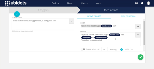
Select the Then actions tab to execute the planned Event or Alert such as Email, SMS, Telegram, Voice Call, Slack, or Webhook.
Click on add new action, Select and Configure which actions are to be executed and the message for the receiver. Available actions include Email, SMS, Telegrams, Voice Call, Set Variable, SLACK, or WebHooks.

For this solution I would like to configure Email, SMS, Telegrams, Voice Call, First of all, I would like to configure email.
Enter the Email address, we can add 2 or more emails by simply separating them with a comma. then type the alert mail subject and message as you wish. you can also Add Specific Data Inputs like Variable Name, Device Label, Trigger Value, Trigger Timestamp into the Event for the immediate info after configuring the message create it.
likewise, we can configure and create the rest of the alerts like SMS, Telegram Message, and Voice call.
All you have to do is providing the target mobile no along with the country code and the alert message.
For voice call, you can select the voice of the alert message between John and Alice whereas john is a male voice and Alice is a female voice. then the rest of the details are as same as SMS and telegram message.
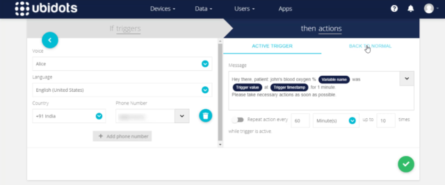
So, all these alerts are triggered when the Spo2 value is less than or equals to 95%, for 1 minute.
After creating an Alert, it is inevitable that the event will be triggered at some point;
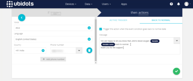
one great feature of Ubidots Events Engine is the “Back to Normal” conditional notification. it will send us another alert if the triggered value came back to normal.
To activate a Back to Normal notification, simply follow the below three steps.
Select the “BACK TO NORMAL” tab from the event’s actions tab.
Select the “Trigger this action” box to verify the desire to receive a “back to normal” notification.
Add the Custom Notification Text as you see fit, then save action.
likewise enable the back to the normal notification to the rest of the Telegram message, SMS, and Email alerts.
After configuring all alerts click on next.
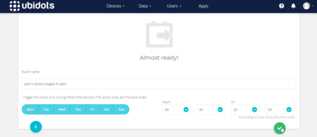
Here you can give a meaningful name to your event and Determine when should the events to be executed and not executed.
For our solution, we have to monitor the patient oxygen levels 24×7 so keep it default and save it.
Now, it’s time to test this event. So come back to the dashboard. here the data can be updated seamlessly.
To make Spo2 less than 95% remove the finger from the top of the sensor, so it will send 0 reading which will satisfy the event condition. then wait for 1 minute, to get event alerts.
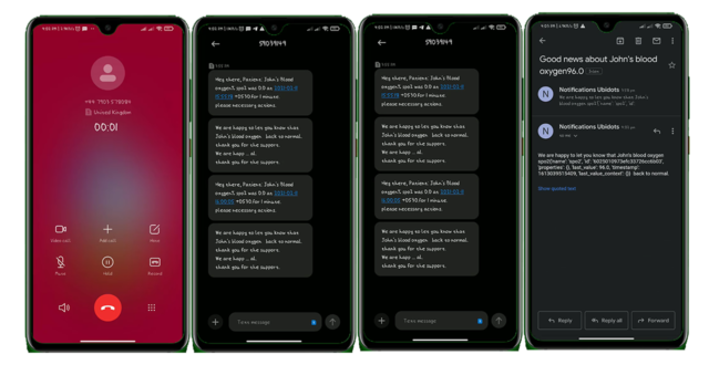
Yesssssssssssssss….. After 1 minute, we have received a voice call from ubidots, Also received the SMS. you can read the text in the below picture which is the same as we configured. We also received telegram message from IoT notifications, maybe IoT notifications is the bot created by ubidots. anyway, we have received the Telegram alert. Mail also received from notifications ubidots, with the Subject and mail body we have configured on the event.
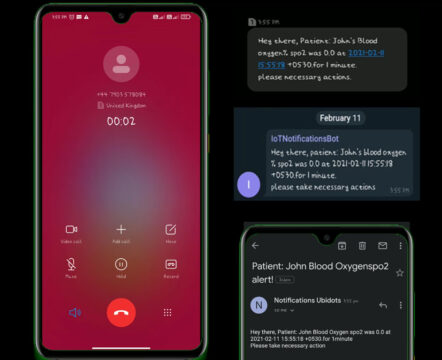
So, all 4 alerts were triggered and sent to the configured receiver. For demonstration, I have provided my mobile no, for real-time scenarios we can simply replace my no with hospital management, patient care takes, or patient loved ones.
Now, it’s time to test the “back to the normal” alert feature.
To make this Spo2 greater than 95% I am gonna place my finger on top of the sensor, so it will send the exact readings of my body which will satisfy the event condition to trigger back to normal alert.
Yesssssssssssssss….. After 1 minute, we have received a voice call from ubididots again, zing zing amazing. I fall in love with this feature. likewise, we have received SMS alert, and Telegram message alert from the IoT notification, also we have received the Mail from notifications ubidots, with the Subject and mail body we have configured on the back to the normal event.
That’s all about developing IoT based Smart Patient Blood Oxygen meter with ESP8266 and sending critical alerts to the hospital management and patient loved ones.
I hope you have learned something new from this episode. Stay tuned to electronics innovation for more interesting projects.
See you on the next interesting episode. bubyeeee…
Video Tutorial: Part 1 Smart Patient Blood Oxygen monitor
Video Tutorial: Part 2 Smart Patient Blood Oxygen monitor
[…] we can also make this device more intelligent by adding an event to trigger an alert whenever a critical situation occurs. This alert includes Voice calls, Messages, Emails, and Telegram messages. This alert can be configured as per the user’s request. Users can configure to send alerts to their family members, care takes, or family doctors. it’s up to them. I have already explained how to configure it, and how will you receive the alerts in the previous tutorial. […]
I did everything according to your video but serial monitor and ubidots kept showing zero value, I check the sensor using arduino it is working fine. what can I do to fix this problem?
Will the code be same for esp32
not getting an alert from ubidots,remaining all the things worked ,can you please help us with it?