Final Product Testing – Recharge Hub – Hardware Development Series
Welcome to the final episode of the Hardware Development series.
In this video, I will perform a continuity checking test for this PCB. if we damage any track or pad while soldering, that can be identified here. Also, we will test the final product “Li-ion batteries recharge hub” whether these batteries will get a full charge or not??? if yes, how much time will take to charge these 4 batteries???
let’s find out now.
Before jumping into the episode, let me thank my favorite PCB Manufacturer, PCBway.com for sponsoring this video.
PCBWay.com is the one-stop solution for PCB Prototyping, Manufacturing, and PCB Assembly. Along with PCB prototype and SMD-Stencils PCBWay is also providing PCB Assembly within 3-4 day production time.
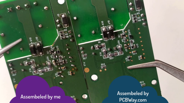
If you are using Very small SMD Components on your PCB, you cannot solder those tiny parts on the PCB, I have struggled a lot to assemble this PCB, But Finally, I have done it. Later I came to know about PCBway Assembling services of PCBway and get this done very easily with few mouse clicks. You can get your PCB Assembled easily from PCBWay.com.
Visit PCBway.com choose PCB Assembly, Quantity, No of unique parts, No of SMT Pads, No of Through holes then click on a quote now.
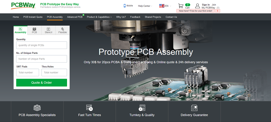
Check other advanced parameters here, then calculate. you can get it at $30 which is the best price in the current industry. Its actual price is 150 USD but currently, they are giving at $30 USD and Also shipping free. In my case, I’m am getting a shipping benefit of 29 USD.
Complete the order, by clicking on the save to cart.
Table of Contents:
Video Tutorial: Final Product Testing – Recharge Hub – Hardware Development Series
PCB Testing:
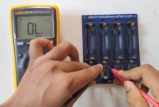
The next step is to perform the continuity check, this test will determine if there is any short circuit between the two opposite polarities, and continuity between the same polarity pads. if we damage any track or pad while soldering, that can be identified here.
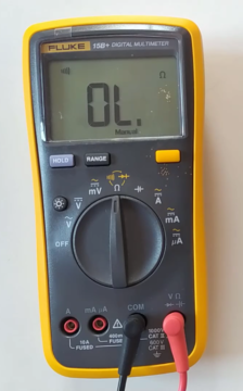
I’m gonna use my fluke 15B+ Digital multimeter in continuity configuration for this test.
I have tested, each and every pad and track of the PCB, The test results are positive, there is no short-circuit between the opposite polarities and there are no damaged tracks.
Now it’s time to celebrate… haha.
The next step is to place batteries and test this recharge hub. so, let’s do that.
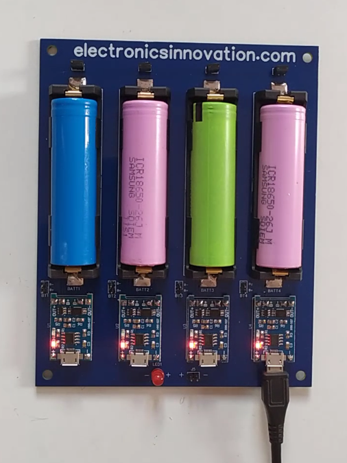
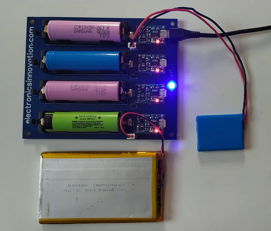
we have to make sure we are placing batteries with the right polarities, otherwise, you will host Diwali here the Battery will get heat and may blast sometimes, so we have to be careful. 4 18650li-ion batteries are placed in the battery holder as shown here.
let’s connect the input power supply and see whether it will charge the batteries or it will host the Diwali.
Yeah, the switch turned on. and the charge controllers started glowing the red led this means, the batteries are being charged. it is a piece of good news for us. but the bad news is the input status led is not glowing. Maybe this one is defective or there will some connection issue. so, let’s debug now.
Soldering new through-hole components on the desoldered through-hole pads will be like hell because the pads will fill with the led, and we have to use a suction gun to takeout the previous led. that will eat your patience and precious time. After 10 mins of struggle, I have replaced this red LED with a Blue one.
let’s connect the input power supply and test again. Yeah… Now, this is working fine, and this proved the previous red led is a defective one.
It is always good practice to disconnect the batteries while debugging something on the PCB. So, I removed all of them. now, let’s turn off the power supply and add the batteries. as you can see here, there is a positive and negative terminal indication on the both battery and Battery holder as well, just follow that and add batteries.
let’s apply the input power supply,
now the charge controller is glowing red led which is indicating batteries are being charged. and the status led is also glowing. Thus the mission accomplished.
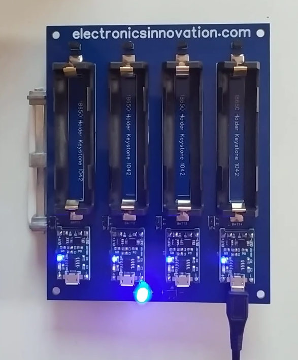
We can simply disconnect the battery, or stop charging the battery by simply removing this jumper. whenever I removed this jumper, the charge controller status led turned to blue, which means, there is no current flowing through it. If the battery is disconnected or the battery fully charged, the amount of current flow through this module will be zero, that’s why it will show a blue led in both cases.
If I connect it, the led will be turned to red.
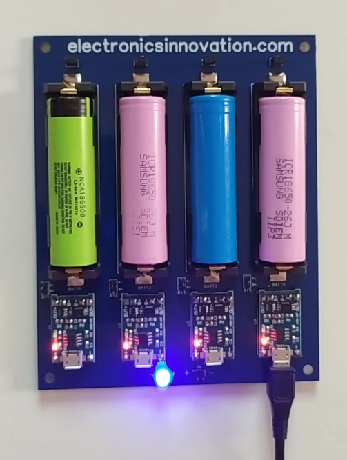
the only thing left is, charging the falt li-ion batteries. let’s test them now. we can easily connect them using the battery connector provided here. So, these batteries are also charging well.
So, the final test.
Are these batteries will get a full charge with this recharge hub??? and how much time this will take to charge these 4 batteries???
let’s find out.
Currently, I am using a 5V 2amp mobile charger, and all Charge controllers are connected parallel to each other. each charge controller is capable of delivering 1 amp. but due to 2amps input and parallel connection, each battery can get only 500 mAmps of current. and the battery is having a 2600mah capacity. So, it should take around 5.2 hours to charge the battery. let’s wait and see how much time it will take???
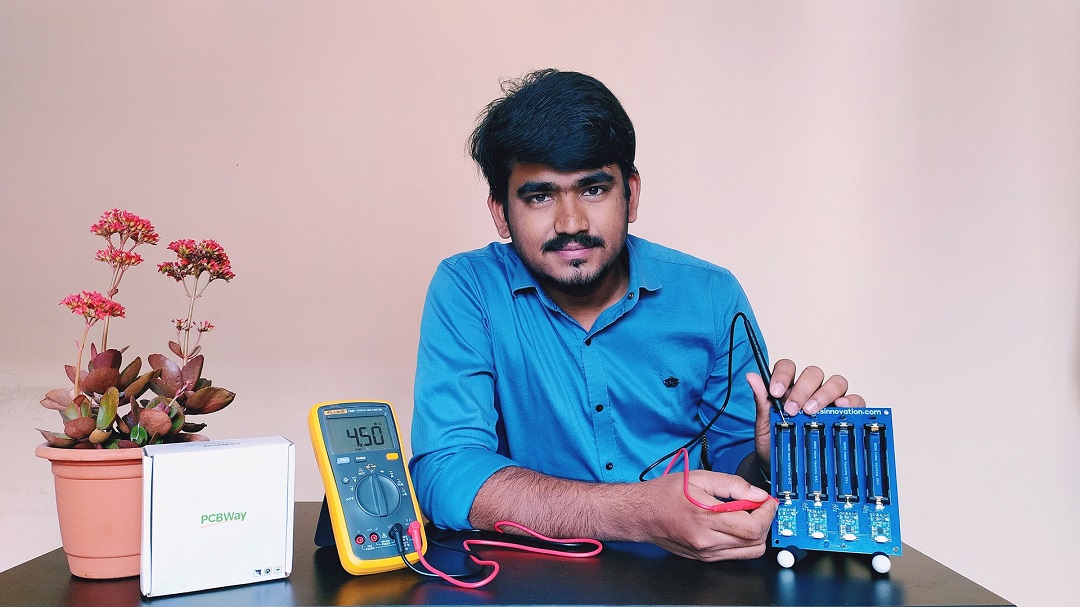
So, after 4.5 hours, the batteries are fully charged. It is quicker than the calculated one. I think these batteries are not fully discharged charged. so, that’s why they have charged fully, before the actual time.

With my knowledge and experience, I can say this recharge hub will take around 6 hours to charge a total of 4 batteries with a 2 amp input power source. because the current flow will not be ideal as our theoretical calculations.
there will be some fluctuation. so, these fluctuations will lead to consuming more power than the calculated on.
So, charging these 4 batteries within 6 hours is okay for me. because I would like to use these batteries for IoT devices. not for the electric vehicles. I have the bandwidth to wait for 6 hours until the batteries are fully charged. If i need these batteries to be charged in lesser time, we can still use the 4 am VOOC charger which will reduce the charging time to 3 hours.
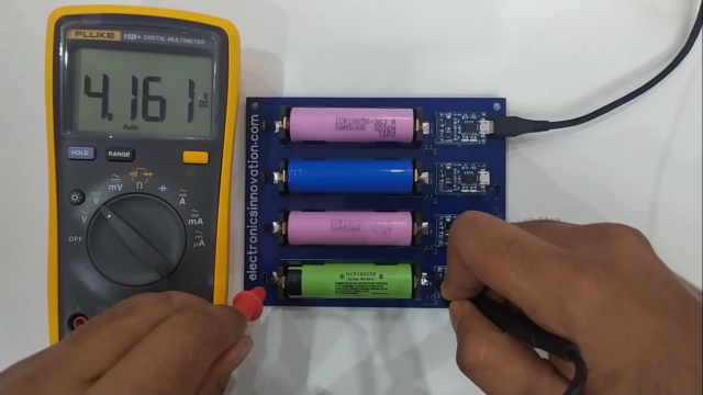
Now, let’s see the voltage of each battery after the full charge. I am gonna use Fluke 15B+ Digital multimeter in DC voltage configuration to measure the voltage of each battery.
The green battery (B1) has 4.161,
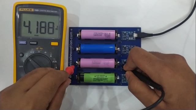
The Pink battery (B2) has 4.188,
The blue battery (B3) has 4.206,

another pink battery (B4) has 4.172.
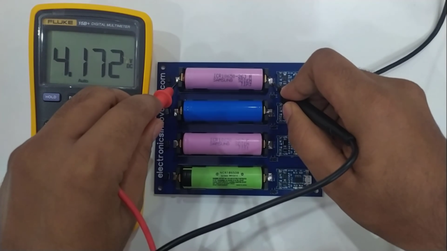
So all the batteries have almost 4.2v which is the maximum voltage level of the Li-ion battery.
Thus the mission accomplished.
That’s it for this tutorial and the hardware development series.
In this journey of hardware development series, we had gone through the component selection and circuit designing of Li-ion battery recharge hub.
also, PCB Designing with Altium designer and PCB manufacturing and its 18 stages of Fabrication process at PCBWay.com. Finally, we have experienced the DIY PCB Assembling process and testing of the hardware after assembly.
I hope this series helped you to learn the basics of hardware development. this is just an ignition through hardware development and a lot to discuss.
I haven’t gone through it very deeply, because that will make things more complex and you will not understand them on the first go. This is just a trailer, Abhi picture bakee hee.
Soo… See you soon on the next interesting episode. bubyeee..