Table of Contents:
Introduction:
LoRa communication with ESP32 & RFM95
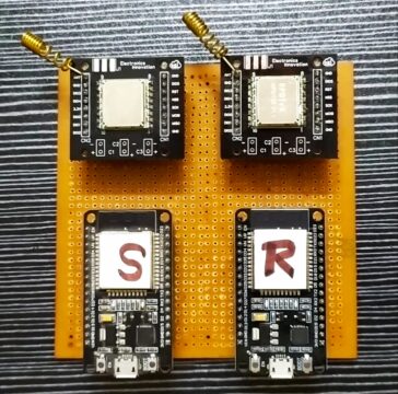
In the previous article, We have learned about LoRa Communication. In this video, we will develop 2 devices for a real-time demonstration of LoRa Communication with RFM95 LoRa module and ESP32 Development kit. These simple LoRa devices are based on Point to point Lora communication topology. In point-to-point communication, two LoRa enabled devices will talk with each other using RF signals.
As an example, we’ll build a simple LoRa Sender and a LoRa Receiver.
The LoRa Sender will be sending a “hello electronics innovation follower ” message followed by a counter for testing purposes. The receiver will receive it and show it on the Serial monitor. Later the same message can easily replace with valuable sensor data.
Video Tutorial: LoRa communication with ESP32 & RFM95
This tutorial is also available in video format, you can watch the below videos or continue reading this article.
Required components: LoRa Communication with RFM95 & ESP32
- RFM95 modules along with Breadboard friendly PCB breakout boards – 2
- ESP32 Modules – 2
- Vero Board
Making RFM95 Lora transceiver PCBWay.com
This RFM95 LoRa transceiver module does not breadboard friendly, which means we cannot solder these 2.54mm male headers to it, or we can place it neither breadboard nor Vero boards. So, I have designed a PCB to make it breadboard-friendly. We can extend the SMD pads of RFM95 with Male headers as shown here. So, that we can place it on both Breadboard and Vero board.
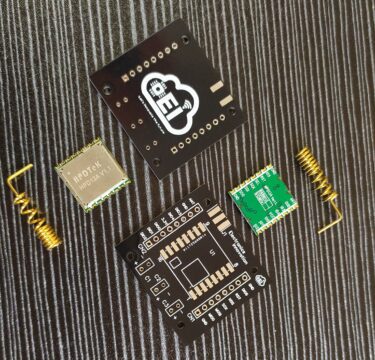
The PCB looks something like that below. The RFM95 module can be soldered on SMD pads. In 3D view PCB looking gorgeous right.
I have generated Gerber files and saved them into the available folder.

PCBWay:
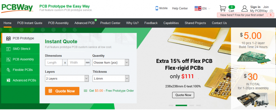
let’s order the PCB on PCBway.com, PCBway.com is an online printed circuit board manufacturing enterprise that turns your DIY breadboard circuits into professional PCBs at just 5 dollars.
To order printed circuit boards visit pcbway.com, Enter Dimensions of PCB, Choose Quantity, select layers and thickness of the PCB then click on the quote now button.
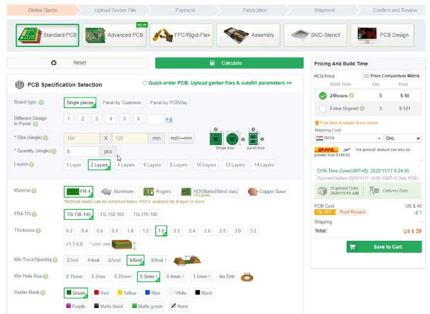
There will be a bunch of options, we have to select them according to our requirements. mostly we don’t have to change anything, we have to make sure of board type, size, and quantity of the PCB, layers, Solder Mask, and Silkscreen. then click on calculate.
Choose the Desired build-time and shipping method, I will choose 2-3days which is a cheaper one. and I will choose Fedx, because of the lesser delivery time. Then click on save to cart.
A popup window will open to upload the Gerber files, simply select the Gerber file from the location and upload it.
The Gerber files:
Gerber Files: Project Outputs for RFM95 Breakout Board
Then submit the order.
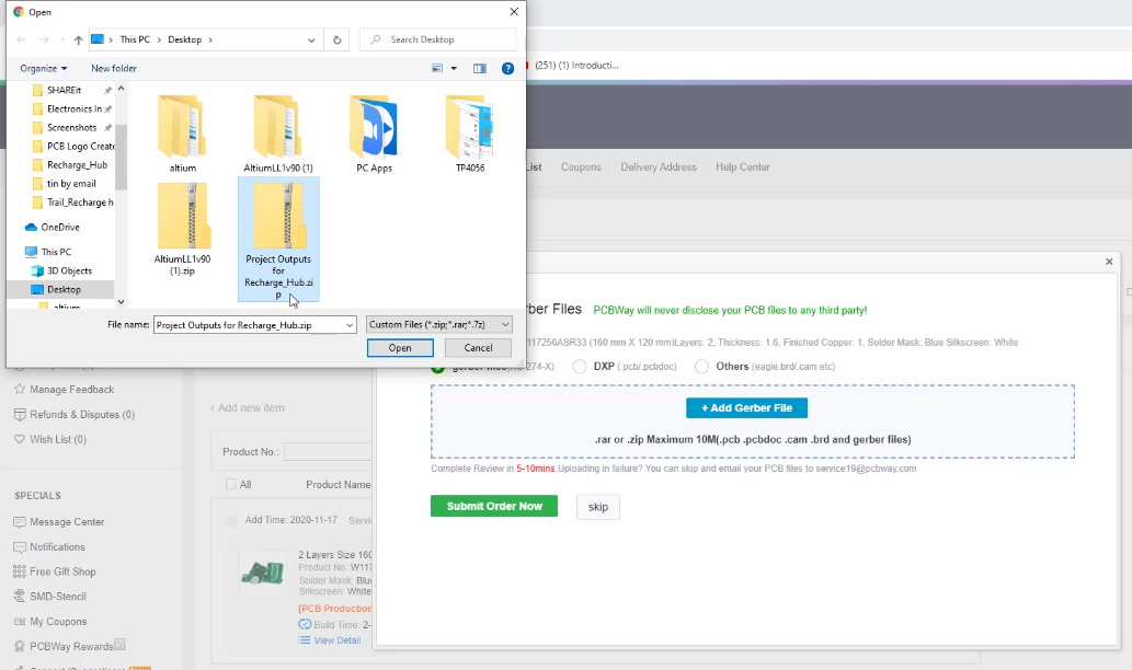
After that, the status of the order will be shown as subject to audit, at this time some folks from PCBway will verify the Gerber file, whether it is good to go, or any manufacturing difficulties are there.
After some time the status will turn to “Pass Payment” this means our PCB is good to go & there are no difficulties.
We can see the preview of the Gerber files here. you can see both top and bottom layer previews as shown here. If you observe quietly, there is a different Battery holder Here than we designed on Altium,
why because I have updated the Gerber files document with the new footprint of the Battery holder, because the previous one has some issues. so finally the PCB gonna look like this.
if everything okay, click on proceed to payment.
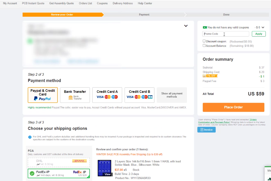
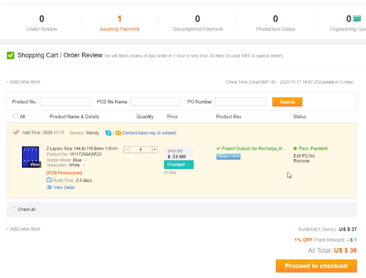 Select favorite mode of payment,
then verify shipping method and PCB details.
If you have any promo codes, discount coupons, you can apply them here. then complete the order by finishing the payment. That’s it.
After successful payment, you can find the order in my orders section, from there we can see the total order details, and also we can track the production status.
That’s it. PCBs ordering process is completed.
This time it took me less than seven days to get my parcel delivered to my lab from PCBway via DHL Courier Service. As I’ve said in a previous video everything comes well packed in the cardboard box.
Unboxing PCB: LoRa Communication with RFM95 & ESP32
This time it took me less than seven days to get my parcel delivered to my lab from PCBway via DHL Courier Service. As I’ve said in a previous video everything comes well packed in the cardboard box.
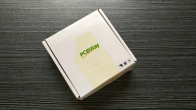
Inside the cardboard box, PCBs are neatly packed in the Vacuum Plastic film packaging. PCBs are so nice, I can feel the softness of the surface of the PCBs when I touch them. The soldering mask and the Silkscreen of the PCBs are very good at quality. additionally, The border finishing added value to the PCBs.
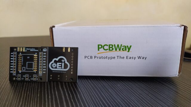
PCBWay.com has been an essential company that supports makers like me around the world building professional PCB projects. they also support some of your favorite YouTubers with their projects. without pcbway, some of the best projects posted online every day wouldn’t be existing/available.
I am feeling grateful to Thank PCBWay for everything they are doing for the maker community.
PCB Assembly:
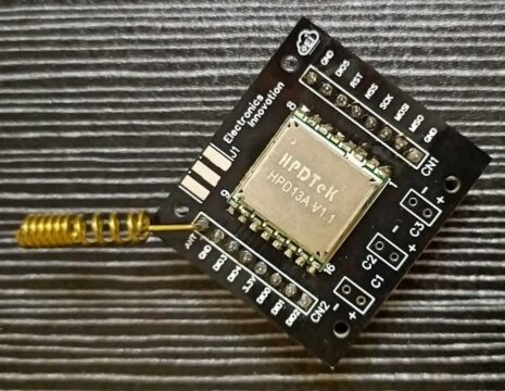
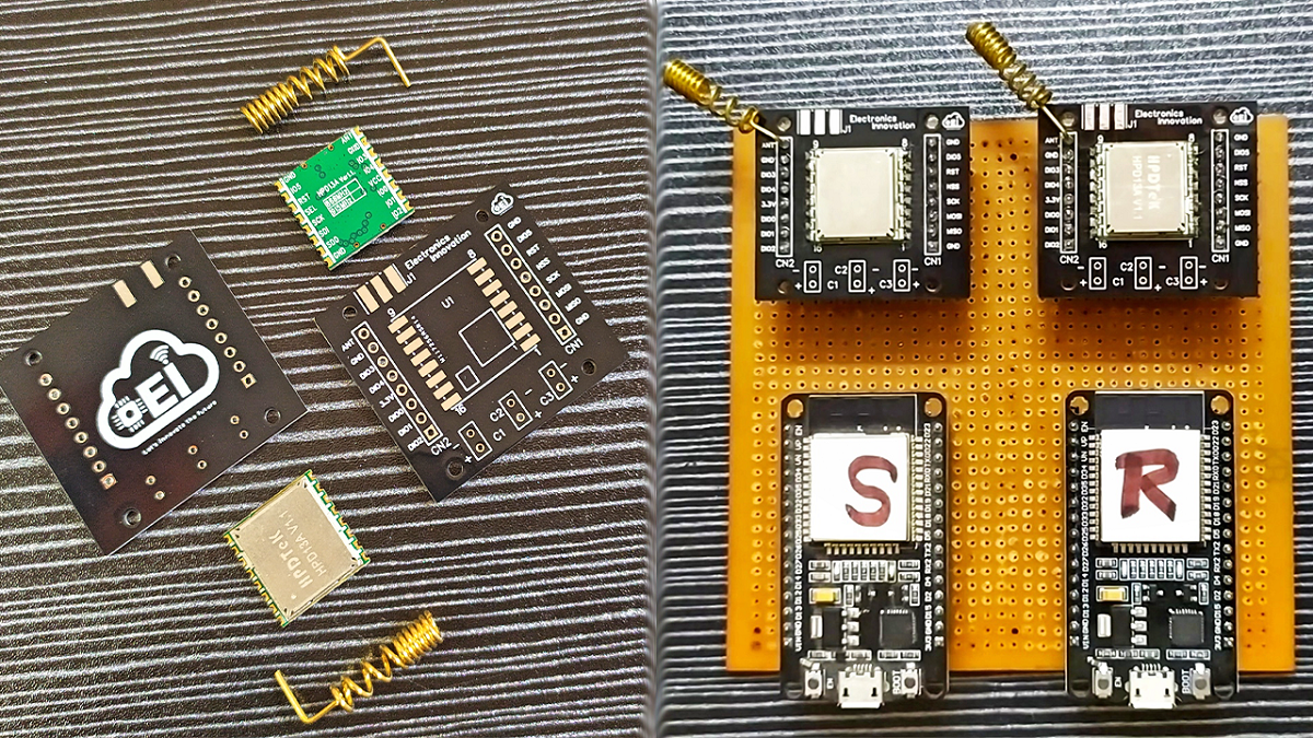
I have soldered RFM95 Module on the PCB, I have followed the standard assembling process to complete the task. Then Soldered Antenna to the ANT pin of the Breakout board. Finally, Soldered male headers to the Breakout board in their respective places.
Then repeated the same process for the other Module.
That’s it. The 2 RFM95 modules are now Breadboard and Vero Boardfriendly.
The Assembled RFM95 module will be as shown below.
Circuit Diagram: LoRa Communication with RFM95 & ESP32
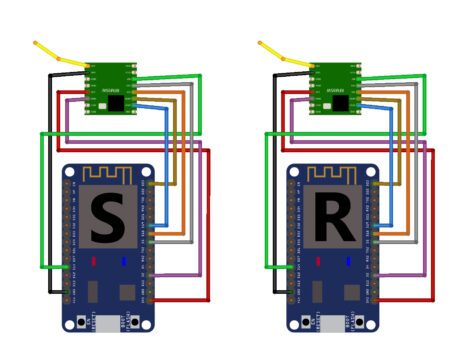
Here is the circuit diagram to interface the RFM95 with ESP32. One is for the sender and One is for the Receiver. if you are not comfortable with soldering, you can still connect the RFM95 with the ESP32 module on Breadboard and continue the project.
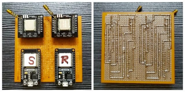
I want to Eliminate the messy wire connections and Make a neat Vero Board PCB for Both devices. I can design a PCB and order on PCBway.com, but I will do it for any specific project with LoRa. I will continue with the Vero board for the simple LoRa Device Demonstration. I made connections between ESp32 and RFm95 with Lead only because this process will eliminate the wire connections. also, This work gives more satisfaction than anything. always do what you love, there only you can find your happiness.
So, After 1 hour of soldering session and dedication; finally, I have completed the connections part. The outcome of the efforts is very satisfying.
Programming part: LoRa Communication with RFM95 & ESP32
The below are the codes for LoRa Communication Sender & Receiver.
As we are using the ESP32 Module, we should have the ESP32 add-on installed in our Arduino IDE. You can Install it from the board’s manager. Suppose you don’t know how to install it. Follow this article.
We are going to use a LoRa Library that is developed by Sandeep Mistry. We can get this library directly from the library manager. install the library from Sandeep Mistry only because I have tested the code with this library only.
ESP32_LoRa_Sender Code:
Copy the below code and paste it into the Arduino IDE and then save it with the name “ESP32_LoRa_Sender”
Before uploading code to the module, check whether the frequency of the Lora Communication is allowed in your country or not. This Lora Communication frequency changes from country to country. You can check the frequency of the Lora allowed in your country by visiting the following page. For example, I am from India, In India it is 865-867Mhz. Specifically, I chose the first suggested frequency of uplink and configured the same. Check your country’s allowed frequency and use the same frequency.
#include <SPI.h>
#include <LoRa.h>

//define the pins used by the transceiver module
#define ss 5
#define rst 14
#define dio0 2

int counter = 0;

void setup() {
  //initialize Serial Monitor
  Serial.begin(115200);
  while (!Serial);
  Serial.println("LoRa Sender");

  //setup LoRa transceiver module
  LoRa.setPins(ss, rst, dio0);

  //replace the LoRa.begin(---E-) argument with your location's frequency
  //433E6 for Asia
  //866E6 for Europe
  //915E6 for North America
  //865E6 -867E6 For India
  while (!LoRa.begin(865.0625E6)) {
    Serial.println(".");
    delay(500);
  }
   // Change sync word (0xF3) to match the receiver
  // The sync word assures you don't get LoRa messages from other LoRa transceivers
  // ranges from 0-0xFF
  LoRa.setSyncWord(0xF3);
  Serial.println("LoRa Initializing OK!");
}

void loop() {
  Serial.print("Sending packet: ");
  Serial.println(counter);

  //Send LoRa packet to receiver
  LoRa.beginPacket();
  LoRa.print("hello Electronicsinnovation follower");
  LoRa.print(counter);
  LoRa.endPacket();

  counter++;

  delay(10000);
}
Testing ESP32_LoRa_Sender Code:
Now, connect one ESP32 Module which you want to program as Sender with Laptop using Micro USB cable. Then go to the ESP32_LoRa_Sender Sketch and Check the Uploading configurations like board: ESP32 Dev Module, Uploading speed, and select the correct port.

If everything is okay, Upload it.
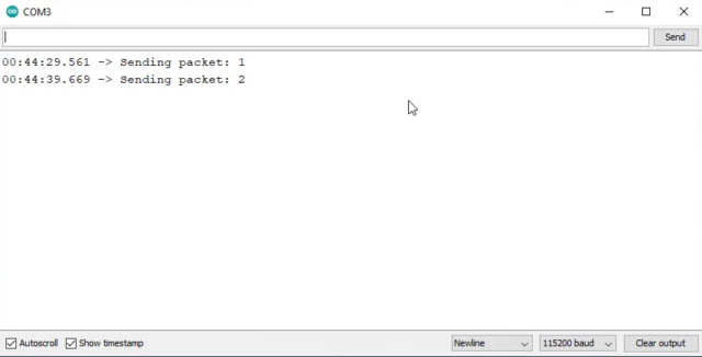
After successfully uploading, Open Serial monitor. IF you see the following text on the Serial monitor, congratulations… You have successfully made a point to point communication topology-based LoRa sender device. This device will send a message “hello Electronicsinnovation follower” followed by a counter every 10 seconds.
ESP32_LoRa_Receiver Code:
Copy the below code and paste it into the Arduino IDE and then save it with the name “ESP32_LoRa_Receiver”
Before uploading code to the module, check whether the frequency of the Sender is matching with Receiver. Otherwise, you never receive a message.
#include <SPI.h>
#include <LoRa.h>

//define the pins used by the transceiver module
#define ss 5
#define rst 14
#define dio0 2

void setup() {
  //initialize Serial Monitor
  Serial.begin(115200);
  while (!Serial);
  Serial.println("LoRa Receiver");

  //setup LoRa transceiver module
  LoRa.setPins(ss, rst, dio0);

  //replace the LoRa.begin(---E-) argument with your location's frequency
  //433E6 for Asia
  //866E6 for Europe
  //915E6 for North America
  while (!LoRa.begin(865.0625E6)) {
    Serial.println(".");
    delay(500);
  }
   // Change sync word (0xF3) to match the receiver
  // The sync word assures you don't get LoRa messages from other LoRa transceivers
  // ranges from 0-0xFF
  LoRa.setSyncWord(0xF3);
  Serial.println("LoRa Initializing OK!");
}

void loop() {
  // try to parse packet
  int packetSize = LoRa.parsePacket();
  if (packetSize) {
    // received a packet
    Serial.print("Received packet '");

    // read packet
    while (LoRa.available()) {
      String LoRaData = LoRa.readString();
      Serial.print(LoRaData);
    }

    // print RSSI of packet
    Serial.print("' with RSSI ");
    Serial.println(LoRa.packetRssi());
  }
}
Testing ESP32_LoRa_Receiver Code:
Connect another ESP32 module that you want to program as a Receiver with a laptop using another Micro USB cable. Then go to the ESP32_LoRa_Receiver Sketch and Check the Uploading configurations like, board: ESP32 Dev Module, Uploading speed, and select another port that is different from the Sender port.

If you face any problem selecting a port, just close the receiver sketch and open it again. then try the same process.
If everything is okay, Upload it.
After successfully uploading the Open Serial monitor. IF you see the following text on the Serial monitor, congratulations… You have successfully made a point to point communication topology-based LoRa receiver device. This device will receive the message sent by the previously programmed sender; The ESp32 will print the message contents on the serial monitor along with RSSI, where RSSI stands for Received Signal Strength Indicator. The RSSI is measured in dBm and is a negative value.
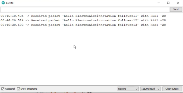
If the RSSI is closer to 0, the better the signal is.
Typical LoRa RSSI values are lies between 0 to -120dbm, If RSSI=-30dBm: signal is strong. If RSSI>=-120dBm: signal is weak.
As you can see here, We are getting around -28 or -27dbm, which means the signal is excellent. Both the devices are next to each of them; that is why the signal strength is good.
That’s all for this tutorial, making a Point to point Lora communication-based LoRa sender and Lora Receiver. I hope you have enjoyed the video and learned something new from this episode.
See you soon on the following innovative project. Until then, Stay tuned to electronics Innovation… Together let’s innovate the future with IoT. byebyeeee
Video Tutorial: LoRa communication with ESP32 & RFM95
[…] That’s all for the deep dive into the LoRa. I hope you have learned some thing ne from this episode. As promised earlier, we should make a LoRa Device now. But due to the long length of the article, we are not doing here. I will write a seperate article on that. You can find that article here. […]
[…] In the previous article, We have talked about What is Lora & LoraWAN, the History of Lora, who invented it??? and How it works?? Later in another article, we have developed point-to-point communication-based LoRa Transceivers with RFM95 LoRa module and ESP32 Development ki…. […]
[…] I have soldered the RFM95 module on the received PCB boards. I have clearly explained this process here. If you wish to have a look check […]
[…] I have soldered the RFM95 module on the received PCB boards. I have clearly explained this process here. If you wish to have a look check […]
HEY I CANNOT GET THE RANGE OF RFM95W UPTO 1 KM. How can I do it.