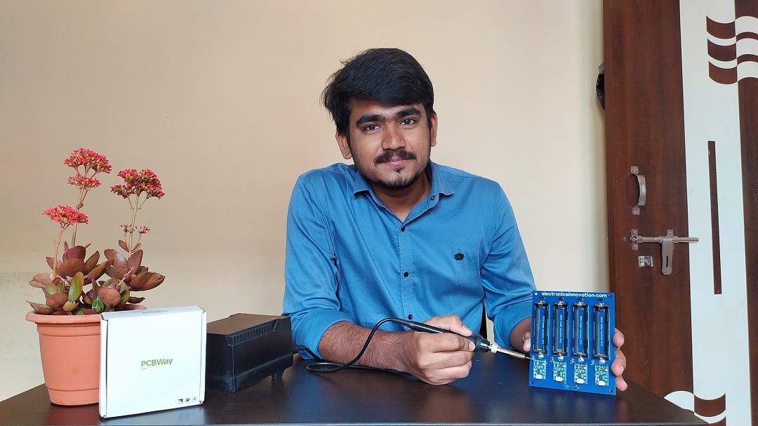
PCB Unboxing & DIY PCB Assembly – Hardware Development series.
Welcome to the Hardware Development series.
In this journey of hardware development series, we had gone through the component selection and circuit designing of the Li-ion battery recharge hub.
also, PCB Designing with Altium designer and PCB manufacturing and its 18 stages of Fabrication process at PCBWay.com in the previous articles.
In this article, I will unbox the package received from PCBWay.com, then we will walk through the Assembling process of the LithiumIon Battery Recharge hub.
So, let’s dive into the episode.
Before jumping into the episode, let me thank my favorite PCB Manufacturer, PCBway.com for sponsoring this video.
PCBWay.com is the one-stop solution for PCB Prototyping, Manufacturing, and PCB Assembly. Along with PCB prototype and SMD-Stencils PCBWay is also providing PCB Assembly within 3-4 day production time.
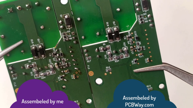
If you are using Very small SMD Components on your PCB, you cannot solder those tiny parts on the PCB, I have struggled a lot to assemble this PCB, But Finally, I have done it. Later I came to know about PCBway Assembling services of PCBway and get this done very easily with few mouse clicks. You can get your PCB Assembled easily from PCBWay.com.
Visit PCBway.com choose PCB Assembly, Quantity, No of unique parts, No of SMT Pads, No of Through holes then click on a quote now.
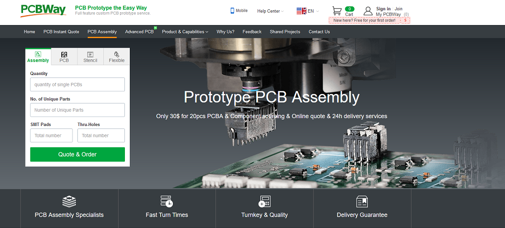
Check other advanced parameters here, then calculate. you can get it at $30 which is the best price in the current industry. Its actual price is 150 USD but currently, they are giving at 150USD and Also shipping free. In my case, I’m am getting a shipping benefit of 29 USD.
Complete the order, by clicking on the save to cart.
Table of Contents:
Video Tutorial: PCB Unboxing & DIY PCB Assembly – Hardware Development series.
This tutorial is also available in video format, you can watch the below videos or continue reading this article.
PCB Unboxing:
After a very long journey, the package from PCBWay.com reached my lab via FedEx courier service. I am eagerly waiting for this, I can’t wait even a single second to see the PCBs. let’s unbox it quickly.
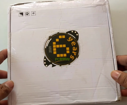
As I have already said in the previous video, the PCBs are neatly packed with bubble wrap using Vaccum film packaging.
Let’s cut it and open it.
As you can see here, the PCBs are high in quality. also, I can feel the softness of the surface of the PCBs.
The Soldering mask and the Silkscreen of the PCBs are very good at quality. The border finishing added value to the PCBs.
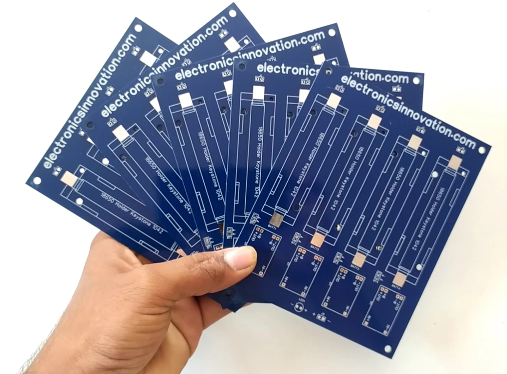
The Gerber files and Bill of materials :
Gerber Files: Project Outputs for Recharge_Hub
Bill of materials:
- 2.54 mm male header – 42pc (Buy On amazon.in)
- 1042p Battery Holders – 4 pc (Buy On amazon.in)
- li-ion battery charge controller(TP4056) – 4pc (Buy On amazon.in)
- LED – 1pc (Buy On amazon.in)
- Soldering Station (Buy On amazon.in)
- Soldering Liquid paste (Buy On amazon.in)
- Soldering Lead (Buy On amazon.in)
- Nipper cutter (Buy On amazon.in)
- PCB Holder (Buy On amazon.in)
PCB Assembly:
The next step is soldering the components to the PCB, I have ordered all required components for this recharge hub from the above-mentioned links.
We are going to solder all these components on the PCB, in the same manner as arranged here.
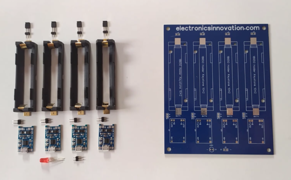
First of all, I will start soldering the lowest high components which is the standard procedure.
In this PCB I will start soldering the jumpers first, then battery connector, and then TP4056 modules along with LED and Input male header last but not lease 18650 battery holder.
So, let’s start it.
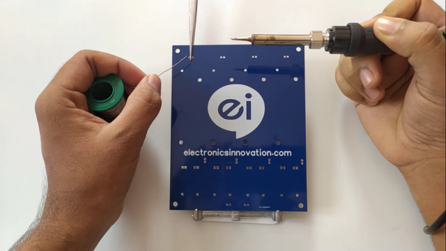
I have placed a male header in its position and used a tweezer to hold it So that I can easily solder as shown here. After soldering, the tweezer can be pulled out. then repeated the same process for the rest of the male headers. So, the 4 male headers soldering is completed. they are sitting on top of the PCB. then the battery connectors are also soldered in their respective places using the same tweezer holding method.
The next step is to mount the TP4056 charge controller module on the PCB with the help of male headers, for that first I have placed all-male headers on the respective places. then TP4056 module mounted, then turned the PCB and soldered male headers to PCB, after that TP4056 module soldered. then simply cut excess male headers with the help of Nipper cutter. then repeated the same process for the rest of the tp4056 modules.
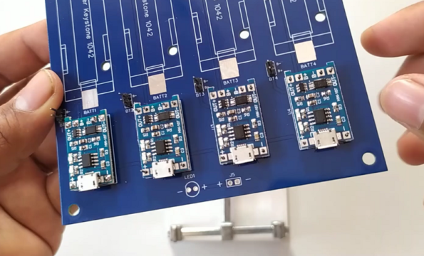
After soldering of all charge controller modules, Input Status Indication LED and Alternative input Male header are soldered as shown here.
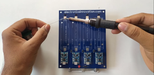
It’s time to solder the 18650 battery holder. Since it is an SMD Component, first we need to pour the lead on the soldering pads, the lead should spread evenly throughout the pad. Then simply place the Battery holder and heat the pad with the help of a little amount of lead. then repeat the same process for all the components.
That’s it assembling process is completed. after all components are assembled, the PCB will be like this.
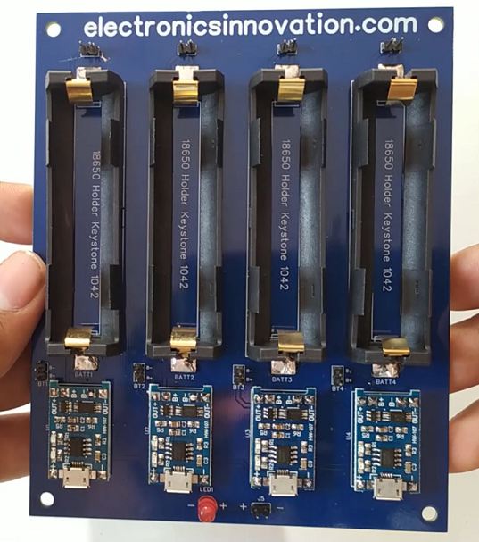
We have to clean the PCB with IPA which is stands for Isopropyl alcohol using a brush to remove the soldering residues. This is the best practice every standard PCB manufacturer suggests.
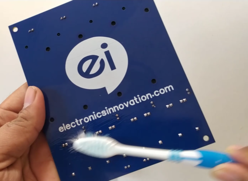
After cleaning, the PCB shining like a diamond. haha just kidding.
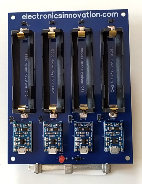
That’s it for this tutorial. In the Next episode, we will perform a continuity checking test for this PCB. if we damage any track or pad while soldering, that can be identified here. Also, we will test the final product “Li-ion batteries recharge hub” whether these batteries will get a full charge or not??? if yes, how much time will take to charge these 4 batteries??? let’s find out in the next Episode.
Soo… See you on the next interesting episode. bubyeee
