Table of Contents:
Introduction:
In this tutorial, we are going to make a ESP32 Cam based Motion Triggered Image Capturing Device with PIR Motion Sensor. we will accommodate all the components on the Vero board and connect them with the soldering lines. This device will send a captured image to a pre-programmed email. This will also save a copy of the captured image in onboard Micro SD Card of ESP32- cam.
This tutorial is also available on the video format, you can watch the below video or continue reading this article.
Required components:
- ESP32 Camera (Buy Online)
- Micro Sd Card (Buy Online)
- FTDI Programmer Module (Buy Online)
- PIR Motion Sensor (Buy Online)
- NPN Transistor (Buy Online)
- 1k and 10k Resistors (Buy Online)
Introduction to ESP32-Cam:
The ESP32-Cam is a very small camera module with the ESP32-S chip that costs less than $10. Besides the OV2640 camera and several GPIOs to connect peripherals, it also features a microSD card slot that can be useful to store images taken with the camera or to store files to serve to clients.
ESP32-Cam Components/parts:
The ESP32-Cam doesn’t have any onboard USB connector like NodeMCU-ESP8266 comes with an onboard micro-USB connector, so you need an FTDI programmer to upload code through the U0R and U0T pins (serial pins).

Feature of ESP32 Camera:
Here is a list with the ESP32-Cam features:
- The smallest 802.11b/g/n Wi-Fi BT SoC module
- Low power 32-bit CPU, can also serve the application processor
- Up to 160MHz clock speed, summary computing power up to 600 DMIPS
- Built-in 520 KB SRAM, external 4MPSRAM
- Supports UART/SPI/I2C/PWM/ADC/DAC
- Support OV2640 and OV7670 cameras, built-in flash lamp
- Supports image WiFI upload
- Support TF card
- Supports multiple sleep modes
- Embedded Lwip and FreeRTOS
- Supports STA/AP/STA+AP operation mode
- Support Smart Config/AirKiss technology
- Support for serial port local and remote firmware upgrades (FOTA)
ESP32-Cam Pinout(AI-Thinker module):

There are three GND pins and two pins for power: either 3.3V or 5V.
GPIO 1 and GPIO 3 are the serial pins. You need these pins to upload code to your board. Additionally, GPIO 0 also plays an important role, since it determines whether the ESP32 is in flashing mode or not. When GPIO 0 is connected to GND, the ESP32 is in flashing mode.
Circuit Diagram:
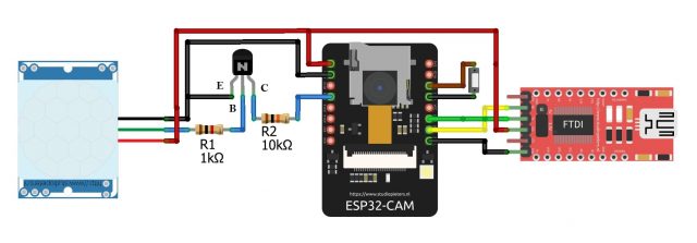
Here is the circuit for ESP32 Cam based Motion Triggered Image Capturing Device, The intermediate trigger circuit between Motion sensor and ESP32 will generate an interrupt to wakeup the ESP32-Cam Module when the motion is detected by PIR Motion Sensor. since ESP32-Cam doesn’t have any onboard USB connector as NodeMCU-ESP8266 comes with an onboard micro-USB connector, we will use this FTDI programmer to upload code through the U0R and U0T pins (serial pins). GPIO0 (IO0) needs to be connected to GND, to put ESP32-Cam in the flash mode so that we can upload code.
I have used Vero board instead of the breadboard to connect all the components, you can use a breadboard there will no issue. After 30 minutes of work with Soldering iron, I have successfully implemented the same circuit on the Vero board.
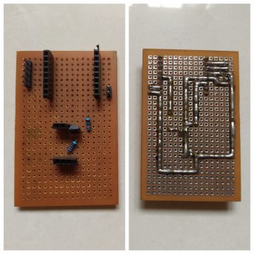
After Placing all the components on the Vero board, It will be something like this.
Note: Before inserting Micro SD Card into ESP32-Cam Module we need to format it.
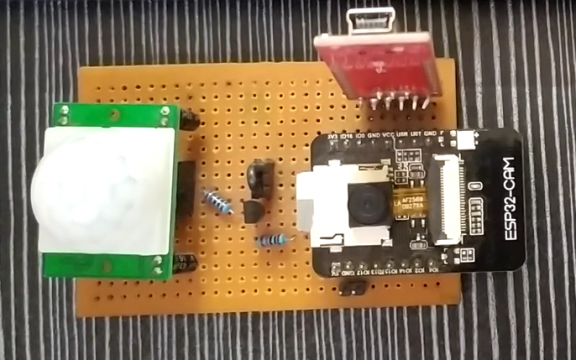
Installing the required libraries and Programming part.
We will use the ESP32 MailClient library to Send the Emails, We’ll program the ESP32 using Arduino IDE.
1. ESP32 add-on Arduino IDE.
In this example, we use the Arduino IDE to program the ESP32-Cam board. So, we need to have Arduino IDE installed as well as the ESP32 add-on. If you haven’t installed the ESP32 add-on in your machine, follow the below tutorials and get it installed.
2. ESP32 Mail Client Library.
To send emails with the ESP32, we’ll use the ESP32 Mail Client library Follow the below instruction to install the library.
In Arduino IDE go to Sketch > Include Library > Manage Libraries…
The Library Manager will open. Search for ESP32 Mail Client by Mobizt and install the library as shown here.

3.Source Code: ESP32 Cam based Motion Triggered Image Capturing Device
Download the code from below Git hub link. but don’t upload it yet. we need to make some changes to make it work. we need to insert the sender’s email address, the recipient’s email address, and network credentials.
link: https://github.com/VeeruSubbuAmi/ESP32_Cam_based_Motion_Triggered_Image_Capturing_Device
The following should change before you upload the code:
Select Camera Module:
We have to select the right camera module here, in my case it is an AI thinker Module. So I have uncommented specific one and commented the rest of the modules.
// Select camera model
//#define CAMERA_MODEL_WROVER_KIT
//#define CAMERA_MODEL_ESP_EYE
//#define CAMERA_MODEL_M5STACK_PSRAM
//#define CAMERA_MODEL_M5STACK_WIDE
#define CAMERA_MODEL_AI_THINKER
Network Credentials
Insert your network credentials in the following lines:
#define WIFI_SSID             "XXXXXXXXX"
#define WIFI_PASSWORD         "XXXXXXXXX"
Email Settings
Enter Sender email credentials like mail id and Password here. For sending emails from ESP32 I don’t prefer to use personal/official Email id. I recommend creating new mail for this. I have explained why we shouldn’t use our personal/official email in my previous video you can refer it for more details. and we have to allow a less secure app for the sender email account. follow the below video if you don’t know how to do it.
link: Email alert based on temperature threshold with ESP32

#define emailSenderAccount    "sender_example@email.com"    //To use send Email for Gmail to port 465 (SSL), less secure app option should be enabled. https://myaccount.google.com/lesssecureapps?pli=1
#define emailSenderPassword   "sender_example_Password"
Insert Recipient email Address, if we wish, we can add more recipient’s address here.
#define emailRecipient        "recipient1_example@email.com"
//#define emailRecipient2     "recipient2@email.com"
We can set Camera parameters here.
//set the camera parameters
sensor_t * s = esp_camera_sensor_get();
s->set_contrast(s, 2);    //min=-2, max=2
s->set_brightness(s, 2);  //min=-2, max=2
s->set_saturation(s, 2);  //min=-2, max=2
delay(100);               //wait a little for settings to take effect
4. Uploading Source Code:
Connect FTDI Module with Computer with help of data cable as shown in the below picture.
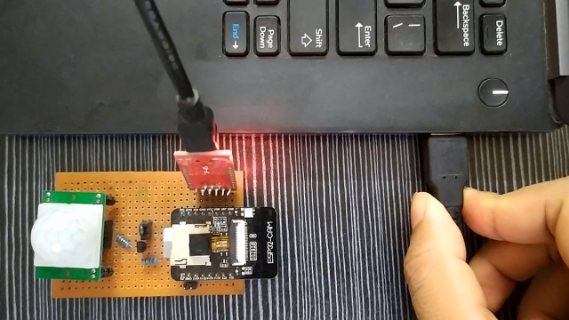
Note: Make sure you have connected IO0 and GND pins to put the ESP32-Cam module in Flash/ Boot mode.
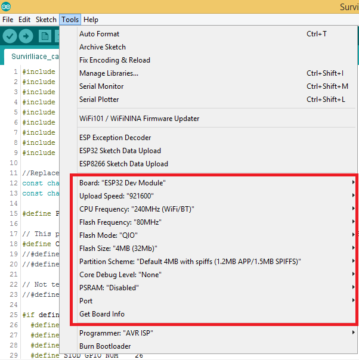
Check the Uploading credentials like board: ESP32 Dev Module, Uploading Speed, and select the right port. If everything okay, upload it.
Testing & Debugging:
After successful uploading, disconnect IO0 and GND pins then, Open Serial Monitor.
On the serial monitor log, you can observe ESP32 successfully connected to the WiFi network. Mounted SD Card successfully and captured an image, and sent an email via SMTP server then went to deep sleep mode.
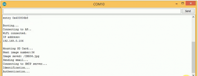

As soon as motion detected, the intermediate circuit will trigger an interrupt to wakeup the ESP32 from Deep Sleep mode. Here you can see as soon as I moved my hand over the sensor the ESP32 wakeup and captured the image and sent an email over the internet successfully then went back to deep sleep mode.
You can see this in the video mentioned at the end of the article.
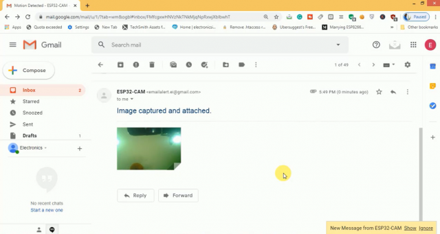
On the Gmail, I have received an email from ESP32 Cam with an attachment of the captured image.
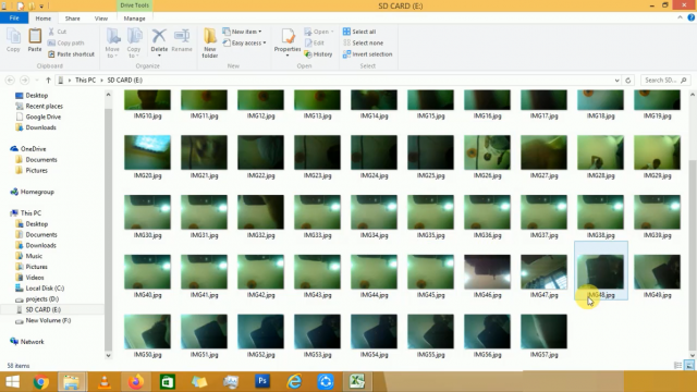
On the other hand, this device also saved a copy of all the capture images in onboard SD Card of ESP32 Camera Module. This feature will help you to have a backup if the internet is disconnected.
Power Source:
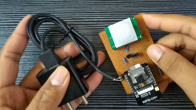
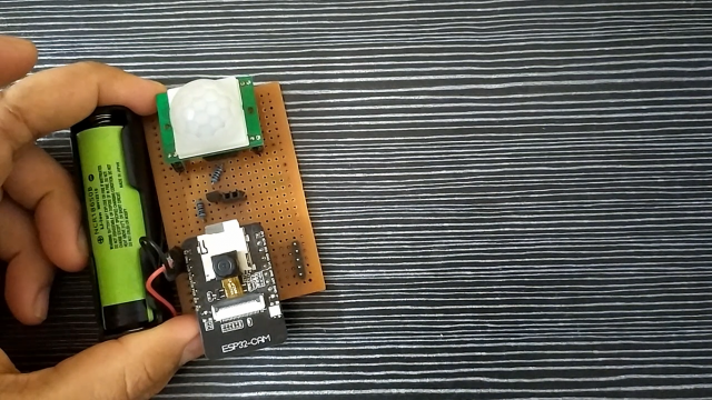
Coming to input power connection you can use any 5v 1A Adapter with a soldered female jumper to connect with the module or you can use any 3.7v batteries like Li-ion or Li-po batteries which can be connected like this.
Summary:
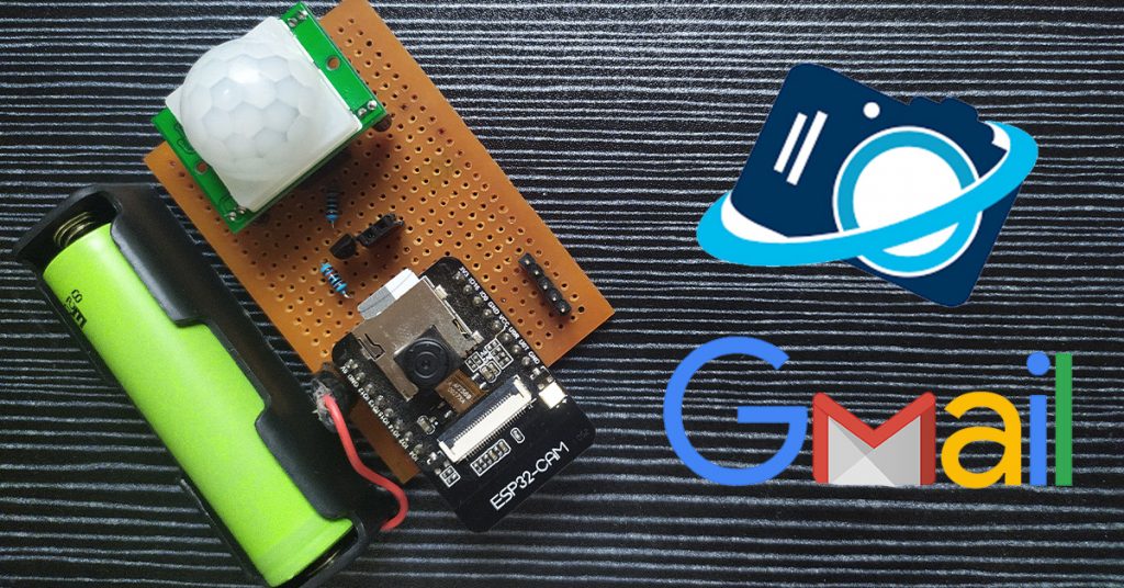
That’s it, our Motion triggered Image capturing cum email device is ready. You can install this at any surveillance area, It will simply capture an image and send an email if any human motion is detected.


[…] Blynk app-based Security Camera with Motion Detection. in my previous articles, I have gone through sending email and telegram alert whenever the motion is detected, but in those projects, there is no way to […]
Hello, when I connect emitter of NPN to VCC then its working. connecting it to GND isn’t working! Why?
operating voltage is 5v for the pir sensor how do you make it work with 3.3v from the battery??