Table of Contents:
Overview:
This Tutorial ” Controlling LED from AWS using NodeMCU & Arduino IDE. ” is all about Controlling Peripherals like AC Appliances and Simple LED from AWS IoT using NodeMCU and ArduinoIDE over MQTT Protocol. In this process, we will walk through how to create a thing in AWS IoT core, generating certificates and policy, How all AWS IoT core credentials are converted to .der format and directly downloaded into the NodeMCU ESP8266 SPIFFS file system.
We will develop a sketch that will establish the connection between ESP8266 and AWS IoT Core using MQTT Protocol.
this sketch requires the certificate files to be uploaded to the device’s flash rather than storing them inline with the script. This allows the same script to be used by multiple devices, that each read the required files from their internal flash storage.
You can watch the following video or continue to the reading of the below-written article
Introduction to AWS IoT Core:
Internet of Things (IoT) is being integrated with almost every device nowadays. There is a number of hardware and software IoT platforms are available in the market for building IoT based application. In my previous article, I have explained how to interface DHT22 with NodeMCU and post the Temperature and Humidity to the Thingspeak webserver. Likewise, we can interface sensors to the hardware development kits like ESP32, ESP8266, Raspberry Pi, Particleboards( Aargon, Boron, Xenon) and post data to the clouds like Thingspeak, Ubidots, AWS IoT Core, Microsoft Azure.
Amazon is not only in e-commerce but also focusing on IoT and providing cloud-based service named as AWS IoT. Here, AWS IOT stands for Amazon Web Service Internet of Things. This service allows us to connect our devices to the internet for processing, operating and exchanging data securely. Along with AWS IoT, the Amazon Web Services also provides tons of other features like virtual machine deployment, web-hosting, etc.
I have also made a tutorial on Temperature Data record on AWS IoT Core with NodeMCU-ESP32 using Arduino IDE and MQTT Protocol. This is Purely based on ESP32.
For ESP8266 related stuff, you can check out the following articles.
- How to connect NodeMCU ESP8266 with AWS IoT Core using Arduino IDE & MQTT
- Storing ESP8266 data into Amazon DynamoDB using AWS IoT Core(MQTT) & Arduino
Requirements for Controlling LED from AWS:
- NodeMCU-ESP8266 Buy from Amazon
- Data Cable Buy from Amazon
- LED
- NPN Transistor(BC547)
- 10K Resistor
- Relay Module
- Bulb Holder + 220V LED/Tungsten Bulb
- Plug
- An active account on Amazon Web Services(AWS).
- Arduino IDE installed on your computer with ESP8266 board configuration
1. Creating a Thing in the AWS IoT Core, generating a certificate and attaching a policy to it.
Check the following Tutorial: How to create a thing in AWS IoT Core, its Certificates & policies
Setting up the AWS environment for these devices is pretty simple. check the following: Amazon AWS
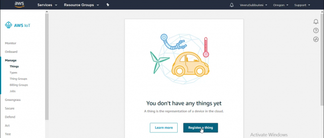
and login to the AWS Management Console & search for IoT core in the Amazon Services, Find services search bar will help you in this regard. After getting into the IoT Core section, tap on the tab called “Manage” from the AWS IoT menu which is on the left side, tap on the register thing button if you haven’t added any devices till now. If you have previously added things just tap on the button named “Create” which is on the top right corner beside the iot-notifications Icon.
Opt to create a single thing and Give your thing name, scroll down and tap on the Next button and then you are immediately offered the one-click certificate generation option. An individual X.509 certificate per device is the recommended way of interacting with AWS IoT services from devices, offering the ability to burn the private key into the device upon enrolment that is then never transferred across the internet alongside requests, a security win. Download the certificate and private key for each device, and also a root CA. Make sure to hit that activate button so the certificate can be used. finish the process by clicking on the “Done” button. If you need any assistance in this regard you can check the video tutorial.

Next point is to create and attach a policy to the certificate, authorizing the authenticated device to perform IoT actions on IoT resources. for this tap on the “secure” tab from the AWS IoT menu which is on the left side, later go for the policies section. Now tap on the button named “Create” which is on the top right corner beside the iot-notifications Icon. give your policy name and fill the fields(Action, Resource ARN ) with a star “*” and check to Allow for Effect option then press the “create” button.
Now tap on the certificates section which is right above the policies section, You will see a certificate which you have created earlier, tap on the three dots and choose to attach the policy, a pop will come showing your existing policies, check on the recent policy that you have created and attach. That’s it you have successfully created a thing, generated a certificate and attached policy to it.
2.Converting AWS IoT Core credential(Certificate, Private Key, Root CA) from .pem to .der format
There are two main methods for encoding certificate data.
- DER = Binary encoding for certificate data
- PEM = The base64 encoding of the DER-encoded certificate, with a header and footer lines added.
DER
DER: (Distinguished Encoding Rules) is a subset of BER encoding providing for exactly one way to encode an ASN.1 value. DER is intended for situations when a unique encoding is needed, such as in cryptography, and ensures that a data structure that needs to be digitally signed produces a unique serialized representation.
PEM
PEM: (Privacy-enhanced Electronic Mail) Simply a US-ASCII by base64 encoded DER certificate, certificate request, or PKCS#7, enclosed between typical PEM delimiters. ie “—–BEGIN CERTIFICATE—–” and “—–END CERTIFICATE—–“. PEM is an abbreviation for Privacy Enhanced Mail (RFC 1421 – RFC 1424), an early standard for securing electronic mail (IRTF, IETF). PEM never has been widely adopted as Internet Mail Standard but has become a staple standard in x509 pki (also called pkix)
Since our ESP8266 will not understand base64 encoding we will convert that certificate to Binary
Installing OpenSSL
The first thing to do is to make sure your system has OpenSSL installed: this is a tool that provides an open-source implementation of SSL and TLS protocols and that can be used to convert the certificate files into the most popular X.509 v3 based formats. here we will use it to convert the .pem files to .DER.
OpenSSL on Linux
If you’re using Linux, you can install OpenSSL with the following YUM console command:
$ yum install openssl
If your distribution is based on APT instead of YUM, you can use the following command instead:
$ apt-get install openssl
OpenSSL on Windows
If you’re using Windows, you can install one of the many OpenSSL open-source implementations: the one we can recommend is Win32 OpenSSL by Shining Light Production, available as light or full version, both compiled in x86 (32-bit) and x64 (64-bit) modes. You can install any of these versions, as long as your system supports them.
IMPORTANT: OpenSSL for Windows requires the Visual C++ 2008 Redistributables runtime in order to work.
OpenSSL is basically a console application, meaning that we’ll use it from the command-line: after the installation process completes, it’s important to check that the installation folder (C:\Program Files\OpenSSL-Win64\bin for the 64-bit version) has been added to the system PATH (Control Panel > System> Advanced > Environment Variables): if it’s not the case, we strongly recommend to manually add it, so that you can avoid typing the complete path of the executable every time you’ll need to launch the tool.
Once OpenSSL will be installed, we’ll be able to use it to convert our SSL Certificates in various formats.
Now go to the folder where all the certificates are downloaded, The AWS certificate will be something like this “xxxxxxxxxx-certificate.pem.crt.txt” So now just rename that document to “xxxxxxxxxx-certificate.pem.crt”.
The following commands will convert the downloaded device certificate files to the correct format for this script.
> openssl x509 -in xxxxxxxxxx-certificate.pem.crt -out cert.der -outform DER
> openssl rsa -in xxxxxxxxxx-private.pem.key -out private.der -outform DER
> openssl x509 -in AmazonRootCA1.pem -out ca.der -outform DER
Replace “xxxxxxxxxx” with your certificate name and AmazonRootCA1 will remain the same because there is no change
Example:
> openssl x509 -in 2b495edf21-certificate.pem.crt -out cert.der -outform DER
> openssl rsa -in 2b495edf21-private.pem.key -out private.der -outform DER
> openssl x509 -in AmazonRootCA1.pem -out ca.der -outform DER
After executing these commands, you will see certificates save in the same folder with .der format, copy these DER-format files into a folder called data
3.Installing ESP8266 sketch data upload tool in Arduino IDE
Before going to ESP8266 sketch data upload tool make sure, your machine has the latest Arduino IDE installed locally, with the ESP8266 plugin installed. If you don’t know how to install ESP8266 plugin,
check out this article: NodeMCU programming with Arduino.
Now Let’s install Arduino ESP8266 filesystem uploader which packs the sketch data folder into the SPIFFS filesystem image, and uploads the image to ESP8266 flash memory.
- Download the tool archive”ESP8266FS-0.4.0.zip” from the Git hub releases page.
- In your Arduino sketchbook directory, create
toolsdirectory if it doesn’t exist yet. You can find the location of your sketchbook directory in the Arduino IDE at File > Preferences > Sketchbook location. - Unpack the tool into
toolsdirectory (the path will look like<sketchbook directory>/tools/ESP8266FS/tool/esp8266fs.jar). - Restart Arduino IDE.
- Select “tools > ESP8266 Sketch Data Upload” will be there.
Credits for this tool: Hristo Gochkov.
4. Arduino sketch and modifications according to the thing for Controlling LED from AWS.
The following Sketch connects your NodeMCU ESP8266 to AWS IoT server then:
– subscribes to the topic “inTopic”, printing out any messages that are coming from the server. also, controls the peripherals like LED/ AC Appliances based on the instruction.
Open a new sketch file of Arduino IDE, Copy & Paste the below code into that and save with some file name. i.e “ESP866_AWS_IoTCore_Peripherals”
You have to make sure that the WiFi username and password are provided which is available in the range.
const char* ssid = "XXXXXXXXXXXXXXXX";
const char* password = "XXXXXXXXXX";
Also, change the AWS_endpoint which is the address of the MQTT broker for your AWS account in a specific region.
const char* AWS_endpoint = "xxxxxxxxxxxxxx-ats.iot.us-west-2.amazonaws.com"; //MQTT broker ip
This AWS_endpoint can be found in the Custom Endpoint section of the Interact tab of your registered things. as shown below.

Make sure files name in the Sketch are matching with the names of your actual certificates in the data folder.
line no: 126> File cert = SPIFFS.open("/cert.der", "r"); //replace cert.crt eith your uploaded file name
line no:141 > File private_key = SPIFFS.open("/private.der", "r"); //replace private eith your uploaded file name
line no:158 > File ca = SPIFFS.open("/ca.der", "r"); //replace ca eith your uploaded file name
We are using the below Function to make our ESP8266 subscribe to the topic “inTopic”, receive any messages/ Commands that are coming from the server and controls the peripherals like LED/ AC Appliances based on the Command/Instruction.
void callback(char* topic, byte* payload, unsigned int length) {
  Serial.print("Message arrived [");
  Serial.print(topic);
  Serial.print("] ");
  for (int i = 0; i < length; i++) {
    Serial.print((char)payload[i]); // Pring payload content
  }
    char led = (char)payload[62]; // Extracting the controlling command from the Payload to Controlling LED from AWS
    Serial.print("led command=");
    Serial.println(led);
    if(led==49) // 49 is the ASCI value of 1
    {
      digitalWrite(D5, HIGH);
      Serial.println("LED_State changed to HIGH");
    }
    else if(led==48) // 48 is the ASCI value of 0
    {
      digitalWrite(D5, LOW);
      Serial.println("LED_State changed to LOW");
     }
  Serial.println();
}
Source Code & Program for Controlling LED from AWS
/*Developed by M V Subrahmanyam - https://www.linkedin.com/in/veera-subrahmanyam-mediboina-b63997145/
Project: Controlling LED from AWS</pre>
<pre> Electronics Innovation - www.electronicsinnovation.com
GitHub - https://github.com/VeeruSubbuAmi
YouTube - http://bit.ly/Electronics_Innovation
Upload date: 11 December 2019
AWS Iot Core
This example needs https://github.com/esp8266/arduino-esp8266fs-plugin
It connects to AWS IoT server then:
- subscribes to the topic "inTopic", and perfprm the action according to the data recieved from the AS
*/
#include "FS.h"
#include
#include //https://www.arduinolibraries.info/libraries/pub-sub-client
#include //https://www.arduinolibraries.info/libraries/ntp-client
#include
// Update these with values suitable for your network.
const char* ssid = "xxxxxxxxxxxxxxx";
const char* password = "xxxxxxxxx";
WiFiUDP ntpUDP;
NTPClient timeClient(ntpUDP, "pool.ntp.org");
const char* AWS_endpoint = "xxxxxxxxxxxxxx-ats.iot.us-west-2.amazonaws.com"; //MQTT broker ip
void callback(char* topic, byte* payload, unsigned int length) {
Serial.print("Message arrived [");
Serial.print(topic);
Serial.print("] ");
for (int i = 0; i < length; i++) {
Serial.print((char)payload[i]); // Pring payload content
}
char led = (char)payload[62]; // Extracting the controlling command from the Payload to Controlling LED from AWS
Serial.print("led command=");
Serial.println(led);
if(led==49) // 49 is the ASCI value of 1
{
digitalWrite(D5, HIGH);
Serial.println("LED_State changed to HIGH");
}
else if(led==48) // 48 is the ASCI value of 0
{
digitalWrite(D5, LOW);
Serial.println("LED_State changed to LOW");
}
Serial.println();
}
WiFiClientSecure espClient;
PubSubClient client(AWS_endpoint, 8883, callback, espClient); //set MQTT port number to 8883 as per //standard
long lastMsg = 0;
char msg[50];
int value = 0;
void setup_wifi() {
delay(10);
// We start by connecting to a WiFi network
espClient.setBufferSizes(512, 512);
Serial.println();
Serial.print("Connecting to ");
Serial.println(ssid);
WiFi.begin(ssid, password);
while (WiFi.status() != WL_CONNECTED) {
delay(500);
Serial.print(".");
}
Serial.println("");
Serial.println("WiFi connected");
Serial.println("IP address: ");
Serial.println(WiFi.localIP());
timeClient.begin();
while(!timeClient.update()){
timeClient.forceUpdate();
}
espClient.setX509Time(timeClient.getEpochTime());
}
void reconnect() {
// Loop until we're reconnected
while (!client.connected()) {
Serial.print("Attempting MQTT connection...");
// Attempt to connect
if (client.connect("ESPthing")) {
Serial.println("connected");
// Once connected, publish an announcement...
client.publish("outTopic", "hello world");
// ... and resubscribe
client.subscribe("inTopic");
} else {
Serial.print("failed, rc=");
Serial.print(client.state());
Serial.println(" try again in 5 seconds");
char buf[256];
espClient.getLastSSLError(buf,256);
Serial.print("WiFiClientSecure SSL error: ");
Serial.println(buf);
// Wait 5 seconds before retrying
delay(5000);
}
}
}
void setup() {
Serial.begin(9600);
Serial.setDebugOutput(true);
// initialize digital pin LED_BUILTIN as an output.
pinMode(D5, OUTPUT);
setup_wifi();
delay(1000);
if (!SPIFFS.begin()) {
Serial.println("Failed to mount file system");
return;
}
Serial.print("Heap: "); Serial.println(ESP.getFreeHeap());
// Load certificate file
File cert = SPIFFS.open("/cert.der", "r"); //replace cert.crt eith your uploaded file name
if (!cert) {
Serial.println("Failed to open cert file");
}
else
Serial.println("Success to open cert file");
delay(1000);
if (espClient.loadCertificate(cert))
Serial.println("cert loaded");
else
Serial.println("cert not loaded");
// Load private key file
File private_key = SPIFFS.open("/private.der", "r"); //replace private eith your uploaded file name
if (!private_key) {
Serial.println("Failed to open private cert file");
}
else
Serial.println("Success to open private cert file");
delay(1000);
if (espClient.loadPrivateKey(private_key))
Serial.println("private key loaded");
else
Serial.println("private key not loaded");
// Load CA file
File ca = SPIFFS.open("/ca.der", "r"); //replace ca eith your uploaded file name
if (!ca) {
Serial.println("Failed to open ca ");
}
else
Serial.println("Success to open ca");
delay(1000);
if(espClient.loadCACert(ca))
Serial.println("ca loaded");
else
Serial.println("ca failed");
Serial.print("Heap: "); Serial.println(ESP.getFreeHeap());
}
void loop() {
if (!client.connected()) {
reconnect();
}
client.loop();
}
5. Circuit for Controlling LED from AWS
Follow the below Circuit diagram and Connect LED to D5 and then connect the NodeMCU with your Computer.

6.Uploading AWS certificates & code to the NodeMCU ESP8266 for Controlling LED from AWS
Make sure that folder data should sit alongside with your Arduino code as shown below, for that you can move data folder into the Arduino code Folder.
Now open your Arduino code for ESP8266 and Select Tools > ESP8266 Sketch Data Upload menu item. This should start uploading the files into the ESP8266 flash file system. When done, the IDE status bar will display the SPIFFS Image Uploaded message. It might take a few minutes for large file system sizes.
Note: Make sure you have selected a board, port, and closed Serial Monitor.
- To save time while uploading to these devices (both code and especially SPIFFS), set the upload baud rate as high as does not produce errors. That was 921600 for my devices, up from the default of 115200, saving a lot of time while iterating.
- If you get errors when trying to upload the certificates to the device flash, you may not have SPIFFS enabled from the Arduino > Tools menu. Any of the SPIFFS storage size values will work, the certificates take up significantly less than 1 MB. All my devices had 4 MB of flash. If you ever change the board type then this setting is lost; I wiped my certificates several times while re-uploading code while I hadn’t noticed this, resulting in connection errors.

Once the Certificates are uploaded successfully, Now go for uploading of the Arduino sketch “ESP8266_AWS_IoTCore” the NodeMCU board by clicking on the upload button of Arduino IDE.
Once the script is uploaded you can view the output on the Serial Monitor. For debugging any potential issues with the certificates and policies, I used the command on this page. This checks the chain of trust between the client certificate and root CA, and checks that a TLS connection can be established. Potential issues could arise from the certificate not being activated in the AWS Console, or the device clock not having synced with the NTP server which prevents certificate validation.
If everything is okay and device connected to AWS server, You will get the following response in the serial monitor

Testing-Publishing commands to the Topic of thing on Amazon Web Services(AWS IoT Core).
It’s time to get back to the AWS IoT Core and publish commands to the topic.
This Publish to a topic bar can be found in the MQTT client section of the Test tab of your AWS IoT column. Tap on that.

Once you tap on the Publish to a topic, It will take you to the Message/Command Publishing section. Just type your topic name”inTopic” in the Specify a topic to publish bar and Copy and paste the following message/Command in the JSON payload field. Then tap on the Publish to a topic button.
{
  "message": "Hello from AWS IoT console"
  "led_Control": "1"
}
Controlling LED from AWS: Demo
As soon as the message/Command published, The NodeMCU will Execute the command either Glowing the LED or Turning it off. In this, I have published “1” so LED will start glowing. You can see the same thing that happened in the picture that is attached Below.

Now Change the “LED_Control” Command to “0” and hit the Publish to a topic button. This LED will Stops Glowing. As shown below.

This is how we are able to control simple LEDs from AWS, So let’s see how we can replicate/Apply the same thing with the AC appliances.
In this context, we need to change the Hardware connection only. we don’t have to change anything in the Code, or from the server-side. Follow the below circuit diagram and connect the components.
After that providing the AC power supply to the circuit.
My circuit will look something like this after all the connections.

Controlling LED from AWS:
Now Come back to the AWS and Publish “LED_Control”: “1”; As soon as the Command published, you will witness the Glowing LED as Shon below.

Publish “LED_Control”: “0”; you will see the LED stops Glowing as Shon below.

You can follow the video to understand the whole process like how to create a thing in AWS IoT core, generating certificates and policy, How all AWS IoT core credentials are converted to .der format and directly downloaded into the NodeMCU ESP8266 SPIFFS file system.
Video Tutorial: Connecting NodeMCU with AWS IoT Core using Arduino IDE.
line 37 i < length,