Table of Contents:
Introduction: IoT based Low-cost ECG & Heart monitoring system
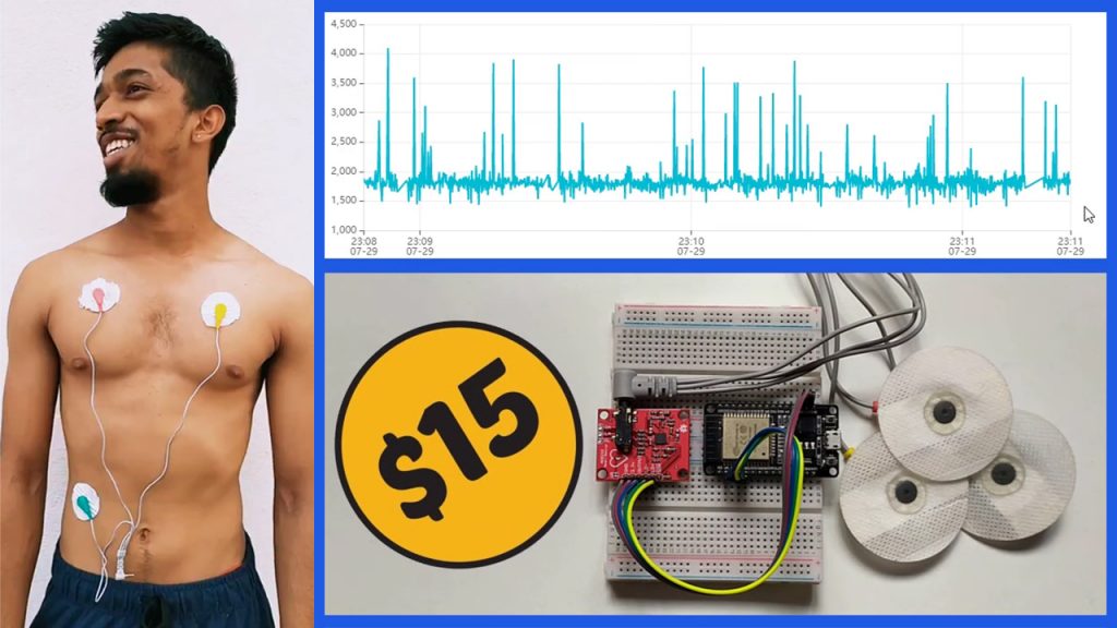
In this video, we will see How to make an “IoT Based Low-cost ECG & Heart monitoring system with esp32 and Ubidots which costs less than $15”
In one of my previous videos, I had gone through how we can make a low-cost ECG monitoring system with Arduino Board. but that project is purely based on offline. You can monitor the ECG signal only when you are present at that system.
So, considering the current scenario, I thought it would be a better solution if I can connect that system with Intenet and make ECG & Heart monitoring possible remotely.
The AD8232 is an integrated signal conditioning block for ECG and other biopotential measurement applications. It is designed to extract, amplify, and filter small biopotential signals in the presence of noisy conditions, such as those created by motion or remote electrode placement. This design allows for an ultralow-power analog-to-digital converter (ADC) or an embedded microcontroller to acquire the output signal easily.
So, So in this project, we will interface AD8232 ECG Sensor with ESP32 Module and observe the ECG signal on Ubidots platform.
PCBway:
The PCBs I’m gonna use in this video are ordered from PCBway.com, PCBWAY is one of the best PCB manufacturers in the current industry.
PCBway is offering services like PCB prototype, SMD Stencil, PCB assembly, Flexible PCBs & Advanced PCBs.
At PCBway.com we can get 10 pieces of 2 layered PCBs at just $5 with 24 hours build time.
The Best part of PCBway is the Instant quote feature, just enter the PCB size, choose the quantity, layers, and thickness. That’s it, we will get the instant quote. place an order by clicking on saving to cart.

This tutorial is also available in the video format, you can watch the below video or continue reading this article.
Required Components :
- ESP32 Module Buy from Amazon
- ECG Module AD8232 Buy from Amazon
- ECG Electrodes – 3 pieces Buy from Amazon
- ECG Electrode Connector -3.5 mm Buy from Amazon
- Breadboards Buy from Amazon
- Connecting wires. Buy from Amazon
Theory:
Before going to interface AECG module AD8232 with ESP32, Let’s see the theory behind the Electrocardiogram & How the heart will pump the blood to the whole body.
The right side of the heart receives venous blood from the body through the superior and inferior vena cava which entered the right atrium. blood flows through the tri custard valve into the right ventricle. Blood leaves the right ventricle through the pulmonary valve into the main pulmonary artery.

The pulmonary artery divides into right and left pulmonary arteries to transport deoxygenated blood from the right side of the heart to the right and left lungs. The pulmonary arteries branch further into the pulmonary cavalry bed where oxygen and carbon dioxide exchange occurs.


The four pulmonary veins two from the right lung and two from the left lung carry oxygenated blood from the lungs to the left side of the heart. The oxygenated blood flows from the left atrium through the mitral valve and into the left ventricle and out through the aortic valve and into the aorta and to the body.


Electrical impulses originate in the Sinoatrial node located at the junction of the right atrium and superior vena cava. Each electrical impulses generated from the SA node travels through the right and left atrium causing the atria to contract. The impulse then travels to the atrial ventricular node A V node then to the bundle of hiss and finally through the right and left bundled branches of the ventricles causing the ventricles to contract.

Electrocardiogram(ECG):

The P wave of electrocardiogram represents atrial contraction. The PR interval is a measure of time from the onset of atrial contraction to the onset of ventricular contraction. The Q R S complex represents the complete depolarization of the ventricles,


The S T segment represents the complete depolarization of the ventricles. elevation or depression of this segment may indicate heart muscle ischemia


The Q T interval represents the complete depolarization and repolarization of the ventricles.
A prolonged Kutty interval is a risk factor for ventricular arrhythmias and sudden death.


Medical uses of ECG
An electrocardiogram can be a useful way to find out whether your high blood pressure has caused any damage to your heart or blood vessels. Because of this, you may be asked to have an ECG when you are first diagnosed with high blood pressure.
Some of the things an ECG reading can detect are:
- cholesterol clogging up your heart’s blood supply
- a heart attack in the past
- enlargement of one side of the heart
- abnormal heart rhythms
AD8232 ECG Sensor
The AD8232 is an integrated signal conditioning block for ECG and other biopotential measurement applications. It is designed to extract, amplify, and filter small biopotential signals in the presence of noisy conditions, such as those created by motion or remote electrode placement. This design allows for an ultralow-power analog-to-digital converter (ADC) or an embedded microcontroller to acquire the output signal easily.

The AD8232 can implement a two-pole high-pass filter for eliminating motion artifacts and the electrode half-cell potential. This filter is tightly coupled with the instrumentation architecture of the amplifier to allow both large gain and high-pass filtering in a single stage, thereby saving space and cost.
An uncommitted operational amplifier enables the AD8232 to create a three-pole low-pass filter to remove additional noise. The user can select the frequency cutoff of all filters to suit different types of applications.

To improve common-mode rejection of the line frequencies in the system and other undesired interferences, the AD8232 includes an amplifier for driven lead applications, such as right leg drive (RLD).
The AD8232 includes a fast restore function that reduces the duration of otherwise long settling tails of the high-pass filters.
After an abrupt signal change that rails the amplifier (such as a leadoff condition), the AD8232 automatically adjusts to a higher filter cutoff. This feature allows the AD8232 to recover quickly, and therefore, to take valid measurements soon after connecting the electrodes to the subject.
The AD8232 is available in a 4 mm × 4 mm, 20-lead LFCSP package.

Performance is specified from 0°C to 70°C and is operational from -40°C to +85°C.
Note: This product is NOT a medical device and is not intended to be used as such or as an accessory to such nor diagnose or treat any conditions.
Circuit Diagram: IoT based Low-cost ECG & Heart monitoring system

AD8232 ECG Sensor Placement on Body:
Follow any of these methods to place electrodes on the human body, but I will follow the second one because of my electrodes shorter size. The closer to the heart, the better the measurement would be. The cables are color-coded to help you identify a proper placement.

Setting up Ubidots:
Before jump into the programming part lets setup the Ubidots Platform for our solution.
Visit ubidots.com, Ubidots is one of the best IoT Platform to connect things and visualize data. as you can see here, Ubidots have wide no of data visualizing options and it has an eye-catching userfriendly interface. Signup by providing all the required details.

Go to my account, Click on devices, create a new device, select blank device, Enter the name for the device then click on this green tickmark to create the device. That’s it the device is successfully created.

Click on the freshly created device,
Click on add variable, then choose Raw option, Now rename this variable with some name. That’s it, variable also successfully created.

To create a dashboard, go to “Data” –> “Dashboards“, Click on the “dashboard” icon in the top-left of the user interface, Keep all fields default and then create it.
Choose on add new widget, you will be prompted with a bunch of data visualization options, choose one among them, I will use a line chart to plot graph using the uploaded payload data from esp32 Module.
Top on add variables, then select the device, and select the variable,
Add a name for the graph. keep the rest of the options default. Later create it.
Since our device didn’t communicate with Ubidots, it will show No Data Found. Once our device started posting data, we can see the data here itself.

Installing ESP32 Add-on, Required Libraries & Programming part.
We’ll program the ESP32 using Arduino IDE. So, we should have the esp32 addon installed in our Arduino Ide.
ESP32 add-on Arduino IDE.
In this example, we use the Arduino IDE to program the ESP32-Cam board. So, we need to have Arduino IDE installed as well as the ESP32 add-on. If you haven’t installed the ESP32 add-on in your machine, follow the below tutorials and get it installed.
Installing Required Libraries:
We are going to use the below-mentioned libraries, First two libraries are pre-installed. we don’t have to install them.
we have to install the other two libraries, We can install them from the Arduino Library manager itself. Goto library manager, type name of the library which is “PubSubClient” and install it. Repeat the same process for NTPClient.
#include <WiFi.h>
#include <WiFiUdp.h>
#include <PubSubClient.h>
#include <NTPClient.h>
Programming part: IoT based Low-cost ECG & Heart monitoring system
Here Is the code for IoT Based Low-cost ECG & Heart monitoring system with esp32 & Ubidots Platform, We need to provide these details, to make this code work with your Ubidots device.
WiFi Credentials:
Provide WiFi SSID and password for Internet Connection.
#define WIFISSID "xxxxxxxxxxxxxxxxx" // Enter WifiSSID here
#define PASSWORD "xxxxxxxxxx" // Enter password here
Ubidots Credentials:
Provide Ubidots token, we can get this from the Ubidots itself. Go to API Credentials. Copy the token and past it over here
Enter MQTT Client name, This can be any alphanumeric string.
Then enter the Variable label & Device label, which we have created on Ubidots earlier.
#define TOKEN "xxxxxxxxxxxxxxxxxxxxxxxxxxxxxxxxxxx" // Ubidots' TOKEN
#define MQTT_CLIENT_NAME "xxxxxxxxxxxxx" // MQTT client Name
#define VARIABLE_LABEL "xxxxxxxxxx" // ubidots variable label
#define DEVICE_LABEL "xxxxxxxxxxxxxx" // ubidots device label
Source code:
#include <WiFi.h>
#include <WiFiUdp.h>
#include <PubSubClient.h>
#include <NTPClient.h>


#define WIFISSID "xxxxxxxxxxxxx" // Enter WifiSSID here
#define PASSWORD "xxxxxxx" // Enter password here
#define TOKEN "xxxxxxxxxxxxxxxxxxxxxxxx" // Ubidots' TOKEN
#define MQTT_CLIENT_NAME "xxxxxxxxx" // MQTT client Name
// * Define Constants
#define VARIABLE_LABEL "xxxxxxxxxxx" // ubidots variable label
#define DEVICE_LABEL "xxxxxxxxxxxxxxxxxxxx" // ubidots device label


#define SENSORPIN A0 // Set the A0 as SENSORPIN

char mqttBroker[]  = "industrial.api.ubidots.com";
char payload[10000];
char topic[150];
// Space to store values to send
char str_sensor[10];
char str_millis[20];
double epochseconds = 0;
double epochmilliseconds = 0;
double current_millis = 0;
double current_millis_at_sensordata = 0;
double timestampp = 0;
int j = 0;
/****************************************
   Auxiliar Functions
 ****************************************/
WiFiClient ubidots;
PubSubClient client(ubidots);
WiFiUDP ntpUDP;
NTPClient timeClient(ntpUDP, "pool.ntp.org");

void callback(char* topic, byte* payload, unsigned int length) {
  char p[length + 1];
  memcpy(p, payload, length);
  p[length] = NULL;
  Serial.write(payload, length);
  Serial.println(topic);
}

void reconnect() {
  // Loop until we're reconnected
  while (!client.connected()) {
    Serial.println("Attempting MQTT connection...");

    // Attemp to connect
    if (client.connect(MQTT_CLIENT_NAME, TOKEN, "")) {
      Serial.println("Connected");
    } else {
      Serial.print("Failed, rc=");
      Serial.print(client.state());
      Serial.println(" try again in 2 seconds");
      // Wait 2 seconds before retrying
      delay(2000);
    }
  }
}

/****************************************
   Main Functions
 ****************************************/
void setup() {
  Serial.begin(115200);
  WiFi.begin(WIFISSID, PASSWORD);
  // Assign the pin as INPUT
  pinMode(SENSORPIN, INPUT);

  Serial.println();
  Serial.print("Waiting for WiFi...");

  while (WiFi.status() != WL_CONNECTED) {
    Serial.print(".");
    delay(500);
  }

  Serial.println("");
  Serial.println("WiFi Connected");
  Serial.println("IP address: ");
  Serial.println(WiFi.localIP());
  timeClient.begin();
  client.setServer(mqttBroker, 1883);
  client.setCallback(callback);
  timeClient.update();
  epochseconds = timeClient.getEpochTime();
  epochmilliseconds = epochseconds * 1000;
  Serial.print("epochmilliseconds=");
  Serial.println(epochmilliseconds);
  current_millis = millis();
  Serial.print("current_millis=");
  Serial.println(current_millis);
}

void loop() {
  if (!client.connected()) {
    reconnect();
    j = 0;
  }
  //sprintf(payload, "%s", "{\"ECG_Sensor_data\": [{\"value\":1234, \"timestamp\": 1595972075},{\"value\":1111, \"timestamp\": 1595971075},{\"value\":2222, \"timestamp\": 1595970075}]}");
  j = j + 1;
  Serial.print("j=");
  Serial.println(j);
  sprintf(topic, "%s%s", "/v1.6/devices/", DEVICE_LABEL);
  sprintf(payload, "%s", ""); // Cleans the payload
  sprintf(payload, "{\"%s\": [", VARIABLE_LABEL); // Adds the variable label
  for (int i = 1; i <= 3; i++)
  {
    float sensor = analogRead(SENSORPIN);
    dtostrf(sensor, 4, 2, str_sensor);
    sprintf(payload, "%s{\"value\":", payload); // Adds the value
    sprintf(payload, "%s %s,", payload, str_sensor); // Adds the value
    current_millis_at_sensordata = millis();
    timestampp = epochmilliseconds + (current_millis_at_sensordata - current_millis);
    dtostrf(timestampp, 10, 0, str_millis);
    sprintf(payload, "%s \"timestamp\": %s},", payload, str_millis); // Adds the value
    delay(150);
  }

  float sensor = analogRead(SENSORPIN);
  dtostrf(sensor, 4, 2, str_sensor);
  current_millis_at_sensordata = millis();
  timestampp = epochmilliseconds + (current_millis_at_sensordata - current_millis);
  dtostrf(timestampp, 10, 0, str_millis);
  sprintf(payload, "%s{\"value\":%s, \"timestamp\": %s}]}", payload, str_sensor, str_millis);
  Serial.println("Publishing data to Ubidots Cloud");
  client.publish(topic, payload);
  Serial.println(payload);
  // client.loop();


}
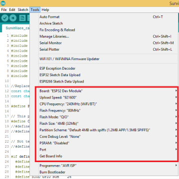
Uploading Source Code:
Connect ESP32 module with Laptop/computer. Check the Uploading configurations like board: ESP32 Dev Module, Uploading Speed, and select the right port. Then upload the code.
Output:
After successful uploading open serial monitor, On the Serial monitor, we can see our ESP32 successfully connected to the programmed wifi and allocated with IP address. Then initiated MQTT connection with Ubidots cloud and connected to it. Then it started publishing ECG data along with a timestamp. Each data packet contains Variable Label and 4 data points with the exact timestamp.

Go to Ubidots and reload it. You can see the live ElectroCardiogram on the Ubidots dashboard. Ubidots receive data from our ESP32 Module and plot the variable on the graph with provided Epoch Timestamp. Since we are sending data with Timestamp, there will be no delay because of server latency on the graph. This helps Ubidots to plot an accurate Electrocardiogram.

Wrapping up:
So, Now anybody from anywhere in the world can monitor the particular person’s heart by just logging into this Ubidots Platform. We made this solution with ES32 and AD8232 Sensor within $15 of the budget.
That’s it for this tutorial, making an IoT Based Low-Cost ECG & Heart Monitoring solution with ESP32 and Ubidots. See you soon on the next interesting project. bubye…
can we use tinkercad instead of physical breadboard? can values can be taken from data set??
Hello sir,
I am trying to develop a project using esp32 ecg and blood pressure monitor using max3000 and sensor you have used here..the thing is that I have got stuck how to combine both of code for them and a single esp32 controlling both of them once at a time by putting a switch so that we can use ones at a time I aslo i want to use a OLED display for display and in ubidots server aslo for better visual perpose… kindly help me our my email [email protected]