Table of Contents:
Overview:
In this project ” DIY Surveillance camera with ESP32-Camera “, we are going to make a DIY Surveillance camera for a home to monitor the surroundings with #ESP32-Camera Module. The ESP32 camera module will host a web server, where we can watch the live streaming of the surveillance are which will help us to know whoever passing by home surroundings.
Video Tutorial:
You can watch the following video or continue to the reading of the below-written article
Required Components:
To follow this tutorial you need the following components:
Introduction to ESP32-Cam:
The ESP32-Cam is a very small camera module with the ESP32-S chip that costs less than $10. Besides the OV2640 camera and several GPIOs to connect peripherals, it also features a microSD card slot that can be useful to store images taken with the camera or to store files to serve to clients.

ESP32-Cam Components/parts:

The ESP32-Cam doesn’t have any onboard USB connector like NodeMCU-ESP8266 comes with an onboard micro-USB connector, so you need an FTDI programmer to upload code through the U0R and U0T pins (serial pins).

Feature of ESP32 Camera:
Here is a list with the ESP32-Cam features:
- The smallest 802.11b/g/n Wi-Fi BT SoC module
- Low power 32-bit CPU, can also serve the application processor
- Up to 160MHz clock speed, summary computing power up to 600 DMIPS
- Built-in 520 KB SRAM, external 4MPSRAM
- Supports UART/SPI/I2C/PWM/ADC/DAC
- Support OV2640 and OV7670 cameras, built-in flash lamp
- Supports image WiFI upload
- Support TF card
- Supports multiple sleep modes
- Embedded Lwip and FreeRTOS
- Supports STA/AP/STA+AP operation mode
- Support Smart Config/AirKiss technology
- Support for serial port local and remote firmware upgrades (FOTA)
ESP32-Cam Pinout(AI-Thinker module):

There are three GND pins and two pins for power: either 3.3V or 5V.
GPIO 1 and GPIO 3 are the serial pins. You need these pins to upload code to your board. Additionally, GPIO 0 also plays an important role, since it determines whether the ESP32 is in flashing mode or not. When GPIO 0 is connected to GND, the ESP32 is in flashing mode.
The following pins are internally connected to the microSD card reader:
-
GPIO 14: CLK
-
GPIO 15: CMD
-
GPIO 2: Data 0
-
GPIO 4: Data 1 (also connected to the on-board LED)
-
GPIO 12: Data 2
-
GPIO 13: Data 3
Configuration of Video Streaming Server:
Follow the below steps to build a video streaming web server with the ESP32-Cam that you can access on your local network.
1. Install the ESP32 add-on
In this example, we use the Arduino IDE to program the ESP32-Cam board. So, you need to have Arduino IDE installed as well as the ESP32 add-on. If you haven’t installed the ESP32 add-on in your machine, follow the below tutorials and get it installed.
Source Code: DIY Surveillance camera with ESP32-Camera
Copy the Below Code and Paste into the fresh Arduino sketch.
Code Credits: Rui Santos
#include "esp_camera.h"
#include <WiFi.h>
#include "esp_timer.h"
#include "img_converters.h"
#include "Arduino.h"
#include "fb_gfx.h"
#include "soc/soc.h" //disable brownout problems
#include "soc/rtc_cntl_reg.h"  //disable brownout problems
#include "esp_http_server.h"

//Replace with your network credentials
const char* ssid = "XXXX";
const char* password = "XXXXX";

#define PART_BOUNDARY "123456789000000000000987654321"

// This project was tested with the AI Thinker Model, M5STACK PSRAM Model and M5STACK WITHOUT PSRAM
#define CAMERA_MODEL_AI_THINKER
//#define CAMERA_MODEL_M5STACK_PSRAM
//#define CAMERA_MODEL_M5STACK_WITHOUT_PSRAM

// Not tested with this model
//#define CAMERA_MODEL_WROVER_KIT

#if defined(CAMERA_MODEL_WROVER_KIT)
  #define PWDN_GPIO_NUM    -1
  #define RESET_GPIO_NUM   -1
  #define XCLK_GPIO_NUM    21
  #define SIOD_GPIO_NUM    26
  #define SIOC_GPIO_NUM    27

  #define Y9_GPIO_NUM      35
  #define Y8_GPIO_NUM      34
  #define Y7_GPIO_NUM      39
  #define Y6_GPIO_NUM      36
  #define Y5_GPIO_NUM      19
  #define Y4_GPIO_NUM      18
  #define Y3_GPIO_NUM       5
  #define Y2_GPIO_NUM       4
  #define VSYNC_GPIO_NUM   25
  #define HREF_GPIO_NUM    23
  #define PCLK_GPIO_NUM    22

#elif defined(CAMERA_MODEL_M5STACK_PSRAM)
  #define PWDN_GPIO_NUM     -1
  #define RESET_GPIO_NUM    15
  #define XCLK_GPIO_NUM     27
  #define SIOD_GPIO_NUM     25
  #define SIOC_GPIO_NUM     23

  #define Y9_GPIO_NUM       19
  #define Y8_GPIO_NUM       36
  #define Y7_GPIO_NUM       18
  #define Y6_GPIO_NUM       39
  #define Y5_GPIO_NUM        5
  #define Y4_GPIO_NUM       34
  #define Y3_GPIO_NUM       35
  #define Y2_GPIO_NUM       32
  #define VSYNC_GPIO_NUM    22
  #define HREF_GPIO_NUM     26
  #define PCLK_GPIO_NUM     21

#elif defined(CAMERA_MODEL_M5STACK_WITHOUT_PSRAM)
  #define PWDN_GPIO_NUM     -1
  #define RESET_GPIO_NUM    15
  #define XCLK_GPIO_NUM     27
  #define SIOD_GPIO_NUM     25
  #define SIOC_GPIO_NUM     23

  #define Y9_GPIO_NUM       19
  #define Y8_GPIO_NUM       36
  #define Y7_GPIO_NUM       18
  #define Y6_GPIO_NUM       39
  #define Y5_GPIO_NUM        5
  #define Y4_GPIO_NUM       34
  #define Y3_GPIO_NUM       35
  #define Y2_GPIO_NUM       17
  #define VSYNC_GPIO_NUM    22
  #define HREF_GPIO_NUM     26
  #define PCLK_GPIO_NUM     21

#elif defined(CAMERA_MODEL_AI_THINKER)
  #define PWDN_GPIO_NUM     32
  #define RESET_GPIO_NUM    -1
  #define XCLK_GPIO_NUM      0
  #define SIOD_GPIO_NUM     26
  #define SIOC_GPIO_NUM     27

  #define Y9_GPIO_NUM       35
  #define Y8_GPIO_NUM       34
  #define Y7_GPIO_NUM       39
  #define Y6_GPIO_NUM       36
  #define Y5_GPIO_NUM       21
  #define Y4_GPIO_NUM       19
  #define Y3_GPIO_NUM       18
  #define Y2_GPIO_NUM        5
  #define VSYNC_GPIO_NUM    25
  #define HREF_GPIO_NUM     23
  #define PCLK_GPIO_NUM     22
#else
  #error "Camera model not selected"
#endif

static const char* _STREAM_CONTENT_TYPE = "multipart/x-mixed-replace;boundary=" PART_BOUNDARY;
static const char* _STREAM_BOUNDARY = "\r\n--" PART_BOUNDARY "\r\n";
static const char* _STREAM_PART = "Content-Type: image/jpeg\r\nContent-Length: %u\r\n\r\n";

httpd_handle_t stream_httpd = NULL;

static esp_err_t stream_handler(httpd_req_t *req){
  camera_fb_t * fb = NULL;
  esp_err_t res = ESP_OK;
  size_t _jpg_buf_len = 0;
  uint8_t * _jpg_buf = NULL;
  char * part_buf[64];

  res = httpd_resp_set_type(req, _STREAM_CONTENT_TYPE);
  if(res != ESP_OK){
    return res;
  }

  while(true){
    fb = esp_camera_fb_get();
    if (!fb) {
      Serial.println("Camera capture failed");
      res = ESP_FAIL;
    } else {
      if(fb->width > 400){
        if(fb->format != PIXFORMAT_JPEG){
          bool jpeg_converted = frame2jpg(fb, 80, &_jpg_buf, &_jpg_buf_len);
          esp_camera_fb_return(fb);
          fb = NULL;
          if(!jpeg_converted){
            Serial.println("JPEG compression failed");
            res = ESP_FAIL;
          }
        } else {
          _jpg_buf_len = fb->len;
          _jpg_buf = fb->buf;
        }
      }
    }
    if(res == ESP_OK){
      size_t hlen = snprintf((char *)part_buf, 64, _STREAM_PART, _jpg_buf_len);
      res = httpd_resp_send_chunk(req, (const char *)part_buf, hlen);
    }
    if(res == ESP_OK){
      res = httpd_resp_send_chunk(req, (const char *)_jpg_buf, _jpg_buf_len);
    }
    if(res == ESP_OK){
      res = httpd_resp_send_chunk(req, _STREAM_BOUNDARY, strlen(_STREAM_BOUNDARY));
    }
    if(fb){
      esp_camera_fb_return(fb);
      fb = NULL;
      _jpg_buf = NULL;
    } else if(_jpg_buf){
      free(_jpg_buf);
      _jpg_buf = NULL;
    }
    if(res != ESP_OK){
      break;
    }
    //Serial.printf("MJPG: %uB\n",(uint32_t)(_jpg_buf_len));
  }
  return res;
}

void startCameraServer(){
  httpd_config_t config = HTTPD_DEFAULT_CONFIG();
  config.server_port = 80;

  httpd_uri_t index_uri = {
    .uri       = "/",
    .method    = HTTP_GET,
    .handler   = stream_handler,
    .user_ctx  = NULL
  };

  //Serial.printf("Starting web server on port: '%d'\n", config.server_port);
  if (httpd_start(&stream_httpd, &config) == ESP_OK) {
    httpd_register_uri_handler(stream_httpd, &index_uri);
  }
}

void setup() {
  WRITE_PERI_REG(RTC_CNTL_BROWN_OUT_REG, 0); //disable brownout detector

  Serial.begin(115200);
  Serial.setDebugOutput(false);

  camera_config_t config;
  config.ledc_channel = LEDC_CHANNEL_0;
  config.ledc_timer = LEDC_TIMER_0;
  config.pin_d0 = Y2_GPIO_NUM;
  config.pin_d1 = Y3_GPIO_NUM;
  config.pin_d2 = Y4_GPIO_NUM;
  config.pin_d3 = Y5_GPIO_NUM;
  config.pin_d4 = Y6_GPIO_NUM;
  config.pin_d5 = Y7_GPIO_NUM;
  config.pin_d6 = Y8_GPIO_NUM;
  config.pin_d7 = Y9_GPIO_NUM;
  config.pin_xclk = XCLK_GPIO_NUM;
  config.pin_pclk = PCLK_GPIO_NUM;
  config.pin_vsync = VSYNC_GPIO_NUM;
  config.pin_href = HREF_GPIO_NUM;
  config.pin_sscb_sda = SIOD_GPIO_NUM;
  config.pin_sscb_scl = SIOC_GPIO_NUM;
  config.pin_pwdn = PWDN_GPIO_NUM;
  config.pin_reset = RESET_GPIO_NUM;
  config.xclk_freq_hz = 20000000;
  config.pixel_format = PIXFORMAT_JPEG;

  if(psramFound()){
    config.frame_size = FRAMESIZE_UXGA;
    config.jpeg_quality = 10;
    config.fb_count = 2;
  } else {
    config.frame_size = FRAMESIZE_SVGA;
    config.jpeg_quality = 12;
    config.fb_count = 1;
  }

  // Camera init
  esp_err_t err = esp_camera_init(&config);
  if (err != ESP_OK) {
    Serial.printf("Camera init failed with error 0x%x", err);
    return;
  }
  // Wi-Fi connection
  WiFi.begin(ssid, password);
  while (WiFi.status() != WL_CONNECTED) {
    delay(500);
    Serial.print(".");
  }
  Serial.println("");
  Serial.println("WiFi connected");

  Serial.print("Camera Stream Ready! Go to: http://");
  Serial.print(WiFi.localIP());

  // Start streaming web server
  startCameraServer();
}

void loop() {
  delay(1);
}
Modification Required in the above Sketch:
You need to make some modifications before uploading the code. Insert your network credentials in the following variables:
const char* ssid = "REPLACE_WITH_YOUR_WIFI_SSID";
const char* password = "REPLACE_WITH_YOUR_WIFI_PASSWORD";
Then, make sure you select the right camera module. In my case, it is AI-THINKER Model.

So, comment on all the other models and uncomment the appropriate one as shown below:
#define CAMERA_MODEL_AI_THINKERNow, the code is ready to be flashed into your ESP32-Cam module.

ESP32-CAM Code Uploading:
Connect the ESP32-CAM board to your computer using an FTDI programmer. Interface ESP32-cam and FTDI Programmes as shown below:
 Note: GPIO 0 needs to be connected to GND so that you’re able to upload code.
To upload the code, follow the next steps:
- Go to Tools > Board and select ESP32 Dev Module
- Go to Tools > Port and select the COM port the ESP32 is connected to
- In Tools > Partition Scheme, select “Huge APP (3MB No OTA)“
- Press the ESP32-CAM on-board RESET button
- Then, tap on the upload button to upload the code
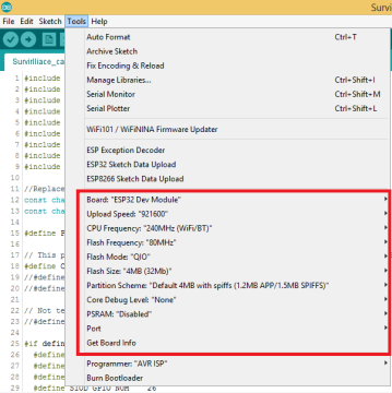
Note: if you can’t upload the code, double-check that GPIO 0 is connected to GND and that you selected the right settings in the Tools menu. You should also press the on-board Reset button to restart your ESP32 in flashing mode.
When you start to see these dots on the debugging window as shown below, press the ESP32-CAM on-board button.

After a few seconds, the code should be successfully uploaded to your board.
Uploading done: Hard resetting via RTS pin…
Don’t be panic, It’s not an error. It is letting us know that the ESP32-Cam is getting reset after the successful uploading of the code. This is the new feature of ArduinoIDE. This feature is available in version 1.8.0 or Above.

Getting Local IP Address of ESP32-Cam Server:
After uploading the code, disconnect GPIO 0 from GND.

Open the Serial Monitor at a baud rate of 115200. Press the ESP32-CAM on-board Reset button.

The Status of the WiFi Connection, Camera module, and ESP32 IP address of the webserver will print in the Serial Monitor as shown below.

Video Streaming Server
Now, you can access your camera streaming server on your local network. Open your favorite browser and key in the ESP32-CAM IP address, then hit the enter button, Video Streaming page will load.
The below picture is the Streaming Page of Full Screen Mode. You can see the picture quality is pretty good. You can feel the frame rate in the Video Tutorial, Checkout the video at the end of the article.

Realtime implementation:
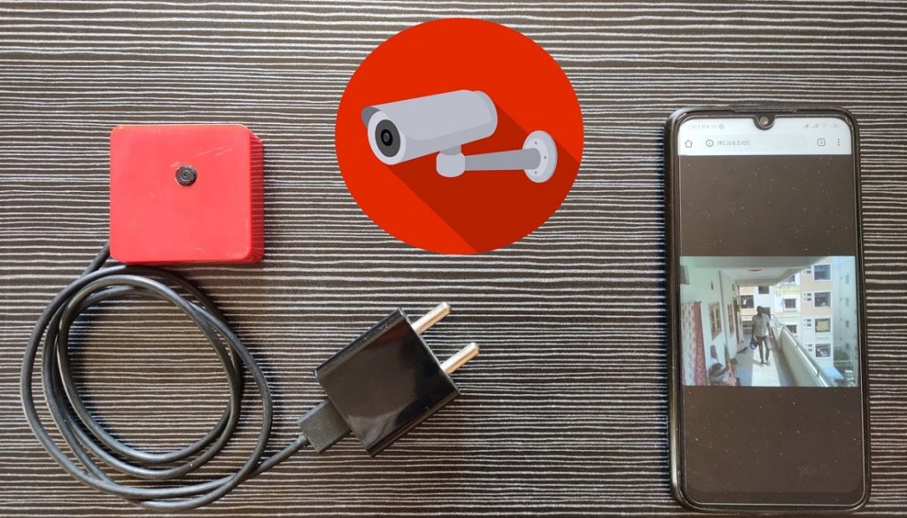
To Protect the Device from Environmental Dust and Humidity when we install at the Surveillance Area, I would like to keep this device in the Casing.
Step 1: Get a Casing where you can accommodate the ESP32 Cam and piece double-sided plaster.

Step2: Accommodate ESP32 Camera inside the casing with the help of plaster as shown below

Step3: Connect the Vin and Ground pins of the ESP32 with 5V 1A Adapter as shown in the below picture.

Step4: Close the casing, The final output will be something like this.

Step5: Get this device install at the surveillance area.

Step6: Live Streaming on the Mobile/ Computer. Visit the Local Webserver IP, You will witness the Live streaming.

Video Tutorial: DIY Surveillance camera with ESP32-Camera
You can watch the following video tutorial for more insights.
hello,
i just followed your steps but its giving me a error after showing” connecting…..___….. “as “Failed to connect ESP32:timed out waiting for packet header” need help immediately…
Press and hold the esp32 boot button while Arduino log showing connecting________…….._________
Then realease the button once it started showing writing 0x000010
Like that.
Hey, I just got these. Mine just says ESP32 and nothing under it. I can’t see the ESP32 espressif add-on in the arduino IDE. Any solutions?