DIY Intelligent Pulse Oximeter for Covid Patients | DIY Pulse Oximeter | MAX30100 | Micropython
The Story:
Recently one of my friends got infected with Corona, The Doctors suggested him for Home Isolation and Prescribed some medication.
Also, they have suggested him to monitor Blood Oxygen levels, and call the Hospital staff if the blood oxygen levels are less than 95%. So that they can take him to the hospital and provide oxygen ventilation.
He is following our channel and liked the previous project called “IoT-based Covid Patient Blood Oxygen monitor” he asked me to develop the same thing, but he suggested some changes like This Oximeter should be worn like a traditional Oximeter and the SpO2 data should be shown on the OLED display.
I agreed with that because his suggestions make sense. previously I made the solution only on the breadboard, which is not portable and he cannot wear it. also, there are no Data readings on the screen. if he want to know the readings, he should open the Ubidots platform and see the data. which is a longer process. So, I thought the suggested changes would make this solution more convenient and robust. So agreed to make changes according to him. Recently, I have learned micro python, so I decided to make this using python only. so that I will get a chance to apply my theoretical learnings to practical applications.
Finally, the device is ready. we can call it as an Intelligent Pulse Oximeter for Covid Patients which is an updated version of the previous solution “IoT-based Covid Patient Blood Oxygen monitor”. This device will monitor patient’s blood oxygen levels and Heart rate then shows them on the OLED display, also it will post data to the Ubidots platform then trigger an alert to medical staff in case of emergency.
Currently, this device is in the prototype stage. I wanted to convert this prototype into a real-time project. hopefully, I will design a PCB and then get that PCB manufactured by PCBWay.com, why because, we all know that PCBWay.com is an online PCB manufacturing company, where we can get the prototype converted into a real-time project and delivered to our home with simple steps. If you wanted to convert your prototype into a real-time project PCBWay.com is the best option. Do check out their website with this link, they have a lot of exciting offers.

So, without wasting further time, Let’s see how did I build this Intelligent Pulse Oximeter.
Table of Contents:
Video Tutorial: Intelligent Pulse Oximeter for Covid Patients
This tutorial is also available in video format, you can watch the below videos or continue reading this article.
Required Components:
1. ESP32 Module (Buy from Amazon)
2. MAX30100 pulse oximeter sensor (Buy from Amazon)
3. 4.7k ohm resistors (Buy from Amazon)
4. OLED Display (Buy from Amazon)
5.Vero Boards (Buy from Amazon)
6. Connecting wires. (Buy from Amazon)
7. Soldering Kit (Buy from Amazon)
8. Cloth Hanging Clips (Buy from Amazon)
Overview: Pulse Oximeter and Heart-Rate Sensor (MAX30100)
Sensor Description:
The MAX30100 is complete pulse oximetry and heart-rate sensor system solution designed for the demanding requirements of wearable devices. The MAX30100 pro-vides very small total solution size without sacrificing optical or electrical performance. Minimal external hardware components are needed for integration into a wearable device. The MAX30100 is fully configurable through software registers, and the digital output data is stored in a 16-deep FIFO within the device. The FIFO allows the MAX30100 to be connected to a microcontroller or microprocessor on a shared bus, where the data is not being read continuously from the device’s registers.

SpO2 Subsystem
The SpO2 subsystem in the MAX30100 is composed of ambient light cancellation (ALC), 16-bit sigma-delta ADC, and a proprietary discrete-time filter. The SpO2 ADC is a continuous-time oversampling sigma-delta converter with up to 16-bit resolution. The ADC output data rate can be programmed from 50Hz to 1kHz. The MAX30100 includes a proprietary discrete-time filter to reject 50Hz/60Hz interference and low-frequency residual ambient noise
Temperature Sensor
The MAX30100 has an on-chip temperature sensor for (optionally) calibrating the temperature dependence of the SpO2 subsystem. The SpO2 algorithm is relatively insensitive to the wavelength of the IR LED, but the red LED’s wavelength is critical to correct interpretation of the data. The temperature sensor data can be used to compensate for the SpO2 error with ambient temperature changes.
LED Driver
The MAX30100 integrates red and IR LED drivers to drive LED pulses for SpO2 and HR measurements. The LED current can be programmed from 0mA to 50mA (typical only) with proper supply voltage. The LED pulse width can be programmed from 200μs to 1.6ms to optimize measurement accuracy and power consumption based on use cases

Benefits and Features
●Complete Pulse Oximeter and Heart-Rate Sensor Solution Simplifies Design
• Integrated LEDs, Photo Sensor, and High-Performance Analog Front -End
• Tiny 5.6mm x 2.8mm x 1.2mm 14-Pin Optically Enhanced System-in-Package
●Ultra-Low-Power Operation Increases Battery Life for Wearable Devices
• Programmable Sample Rate and LED Current for Power Savings
• Ultra-Low Shutdown Current (0.7μA, typ)
●Advanced Functionality Improves Measurement Performance
• High SNR Provides Robust Motion Artifact Resilience
• Integrated Ambient Light Cancellation
• High Sample Rate Capability• Fast Data Output Capability
Applications
●Wearable Devices
●Fitness Assistant Devices
●Medical Monitoring Devices
Circuit Diagram: DIY Intelligent Pulse Oximeter
Here Is the circuit diagram to interface Max30100 and OLED display with ESP32, Since we are using the I2C protocol, both modules can be interfaced with ESP32 with the same Pins. if you want to know, why do we need to solder external pull-up resistors? follow this tutorial.

After Connections, the circuit should be something like this. Don’t worry, I have guided you step by step to make this arrangement in the video tutorial you can refer to the video tutorial for more info.

If you are not interested to make this kind of arrangement, you can still use the breadboard to connect the device as shown here.

Creating device in Ubidots:
Before jump into the programming, part let’s create a device in the Ubidots Platform for our solution. follow the below steps.
- Visit ubidots.com,
- Go to Dashboard,
- Click on devices,
- create a new device, select a blank device,
- Enter the name for the device then click on this green tickmark to create the device.
That’s it the device is successfully created.

Programming part:
Steps to Program ESP32 with Micro Python.
- Setting up ESP32-DevkitC board
- . Setting up the project Pymakr plugin
- . Coding and Uploading program to the ESP32
Setting up ESP32-DevkitC board
To set up ESP32 to program with micropython, first, we have to install ESP-IDF on our computer.
The easiest way to install ESP-IDF’s prerequisites is to download one of ESP-IDF Tools Installers from this URL: https://dl.espressif.com/dl/esp-idf/?idf=4.4
Download and install the ESP-IDF
After installation is done, Run ESP-IDF PowerShell Environment. After that ESP-IDF PowerShell will be opened as shown here.

Next, flash the firmware of the ESP32, Download the latest firmware for the ESP32 module to your PC, and upload the firmware to the ESP32 using the below command.
If you are putting MicroPython on your board for the first time then you should first erase the entire flash using:
esptool.py --chip esp32 erase_flash
From then on program the firmware starting at address 0x1000:
esptool.py --chip esp32 write_flash -z 0x1000 esp32-xxxxxxxx-unstable-v1.15-xx-xxxxxxxxxx.bin
Note: The firmware file should be kept inside the “/esp-idf/” Directory. or you have to redirect to the file location on Powershell.
Now, The ESP32 successfully set up with the Micropython prerequisites. Now. It’s time to write code in micropyton to get data from the sensor and post it to the ubidots platform and then program the ESP32 module.
Before that, we need an Integrated Development Environment to do that. Let’s set up that now.
Visual Studio combined with the Pymaker plugin will get the job done for us.
Setting up the project Pymakr plugin
Pycom supports Microsoft’s Visual Studio Code IDE platform with the Pymakr Plugin.
- First, download and install Visual Studio Code.
- You will also need NodeJS installed on your PC. Please download the latest LTS version available from the NodeJS website. Please follow these steps to install the Pymakr VSCode Extension.
- Ensure that you have the latest VSCode installed and open

- Navigate to the Extensions page, using the 5th button in the left navigation

- Search for Pymakrand click the install button next to it.

- Within a few minutes, a reload button should appear. Press it to reload VSCode.

- That’s it! You’ve installed the Pymakr Extension for VSCode

Coding and Uploading program to the ESP32
Please draft a mail to [email protected] for source code, we will send you.
- After receiving, Now open the Program folder,
- Then Open main.py and boot.py.
- On boot.py, you have to provide Network credentials. Then save it.
- Then come to main.py.

- Now Connect the ESP32 module to the computer with the help of a micro-USB cable.On the terminal, you will see.
Searching for PyCom boards on serial…
Connecting to COM3…Then click the upload button,

- That’s it code successfully uploaded.
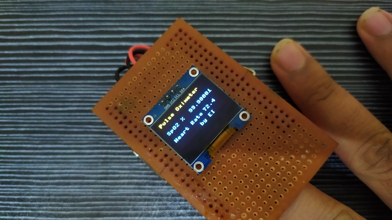
After Successful uploading, the program will automatically run, and you can see the SpO2 and Heart Rate on both the pymaker terminal and OLED Display. So, we have successfully achieved the two suggested changes. Up to this part, every pulse oximeter can do, but here comes the intelligent part of the Oximeter. This oximeter not only displays data on the OLED display. It will also post data to the Ubidots IoT platform using the MQTT protocol.We can see the same data on the Ubidots as Shown here. Heart rate and SpO2 data can be seen like this. I have also added a feature to post the location of the device, its always a good feature to have the location information of the patient so that medical assistance can reach the location early in case of emergency.

we can also make this device more intelligent by adding an event to trigger an alert whenever a critical situation occurs. This alert includes Voice calls, Messages, Emails, and Telegram messages. This alert can be configured as per the user’s request. Users can configure to send alerts to their family members, care takes, or family doctors. it’s up to them. I have already explained how to configure it, and how will you receive the alerts in the previous tutorial.

Isn’t it intelligence? Yes, It is. that’s why I call it as an Intelligent Pulse Oximeter. This can be a life-changing moment for a covid patient who is suffering from low oxygen levels.
I hope you liked this project. This project helped my friend to battle corona, Now he is fully recovered from the corona he is healthy now. Stay home and stay safe. also, Stay tuned to electronics Innovation for more interesting projects. See you on the next interesting episode. bubyeeee…